Chapter: Electrical machines : Synchronous Generator
Parallel Operation of Alternators
Parallel Operation of Alternators
The
operation of connecting an alternator in parallel with another alternator or
with common bus-bars is known as synchronizing. Generally,
alternators are used in a power system where they are in parallel with many
other alternators. It means that the alternator is connected to a live system
of constant voltage and constant frequency. Often the electrical system, to
which the alternator is connected, has already so many alternators and loads
connected to it that no matter what power is delivered by the incoming
alternator, the voltage and frequency of the system remain the same. In that
case, the alternator is said to be connected to infinite bus-bars.
For
proper synchronization of alternators, the following four conditions must be
satisfied
1.
The terminal voltage (effective) of the incoming
alternator must be the same as bus-bar voltage.
2.
The speed of the incoming machine must be such that
its frequency (= PN/60) equals
bus-bar frequency.
3.
The phase of the alternator voltage must be
identical with the phase of the bus-bar voltage. 4. The phase angle between
identical phases must be zero.
It means
that the switch must be closed at (or very near) the instant the two voltages
have correct phase relationship.
Condition
(1) is indicated by a voltmeter, conditions (2), (3) and (4) are indicated by
synchronizing lamps or a synchronoscope.
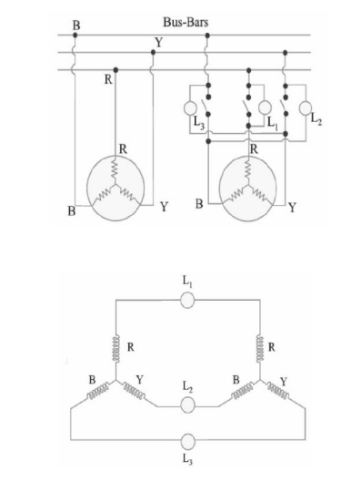
The
synchronizing lamp method is consists of 3 lamps connected between the phases
of the running 3-ph generator and the incoming generator as shown in Fig:
In three
phase alternators, it is necessary to synchronize one phase only, the other two
phases be will then synchronized automatically. However, first it is necessary
that the incoming alternator is correctly 'phased out' i.e. the phases are connected in the proper order of R,Y &B not R, B, Y etc.
Lamp L1
is connected between R and R′, L2
between Y and B′ (not Y and Y′) and L3 between B and Y′ (and not B and B′) as shown in
Fig:


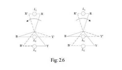
Two set
of star vectors will rotate at unequal speeds if the frequencies of the two are
different. If the incoming alternator is running faster, then voltage star R′ Y′
B′ appear to rotate anticlockwise
with respect to the bus-bar voltage star RYB
at a speed corresponding to the difference between their frequencies. With
reference to Fig: 2.6, it is seen that voltage across L1 is RR′ to be increasing
from zero, and that across L2 is YB′ which is decreasing, having just
passed through its maximum, and that across L3
BY′ which is increasing and
approaching its maximum. Hence the lamps will light up one after the other in
the order 2, 3, 1,2,3,1 or 1, 2, 3. If the incoming alternator is running
slower, then the sequence of light up will be 1, 3, 2. Synchronization is done
at the moment the uncrossed lamp L1
is in the middle of the dark period and other two lamps are equally bright.
Hence this method of synchronization
is known as two bright one dark lamp method.
It should
be noted that synchronization by lamps is not quite accurate, because to a
large extent, it depends on the sense of correct judgment of the operator.
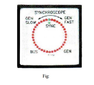
Hence, to eliminate the element of personal judgment in routine operation of
alternators, the machines are synchronized by a more accurate device called a
synchronoscope as shown in Fig: It consists of 3 stationary coils and a
rotating iron vane which is attached to a pointer. Out of three coils, a pair
is connected to one phase of the line and the other to the corresponding
machine terminals, potential transformer being usually used. The pointer moves
to one side or the other from its vertical position depending on whether the
incoming machine is too fast or too slow. For correct speed, the pointer points
vertically up.

Related Topics