Chapter: Electrical machines : Synchronous Generator
Factors affecting the induced emf (Coil Pitch and Distributed Windings) - Synchronous Generator
Factors affecting the induced emf (Coil Pitch and Distributed Windings)
The emf equation derived in art 1.2 and art 1.3 is applicable when the alternator is having full pitch coil and concentrated winding. But when the alternator armature winding is distributed and short pitched then the per phase emf equation will change and become-
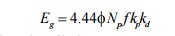
Where Kp is called pitch factor and Kd is called distribution factor.
1. Pitch Factor or Coil Pitch
The ratio of phasor (vector) sum of induced emfs per coil to the arithmetic sum of induced emfs per coil is known as pitch factor (Kp)or coil span factor (Kc) which is always less than unity.
Let the coil have a pitch short by angle q electrical space degrees from full pitch and induced emf in each coil side be E,
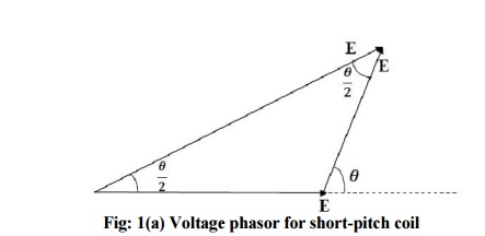
• If the coil would have been full pitched, then total induced emf in the coil would have been 2E
• when the coil is short pitched by q electrical space degrees the resultant induced emf, ER in the coil is phasor sum of two voltages,q apart
Kpn = cos a n where n is the order of harmonic
2. Distribution Factor
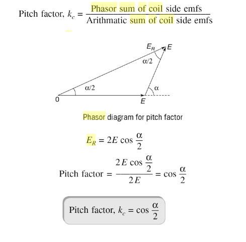
The ratio of the phasor sum of the emfs induced in all the coils distributed in a number of slots under one pole to the arithmetic sum of the emfs induced(or to the resultant of emfs induced in all coils concentrated in one slot under one pole) is known as breadth factor (Kb) or distribution factor (Kd)
The distribution factor is always less than unity.
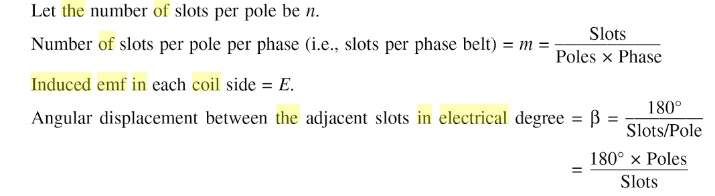
Let no. of slots per pole = Q and no. of slots per pole per phase = q
Induced emf in each coil side = Ec
Angular displacement between the slots, γo
The emf induced in different coils of one phase under one pole are represented by side AC, CD, DE,
EF Which are equal in magnitude (say each equal Ec) and differ in phase (say by γo) from each other.
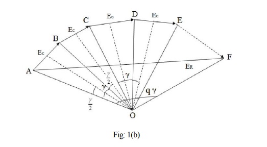
If bisectors are drawn on AC, CD, DE, EF they would meet at common point (O). The point O would be the center of the circle having AC, CD, DE, EF as the chords and representing the emfs induced in the coils in different slots.
3. Harmonic Effect
• The flux distribution along the air gaps of alternators usually is non- sinusoidal so that the emf in the individual armature conductor likewise is non-sinusoidal
• The sources of harmonics in the output voltage waveform are the non- sinusoidal waveform of the field flux.
• Fourier showed that any periodic wave may be expressed as the sum of a d-c component (zero frequency) and sine (or cosine) waves having fundamental and multiple or higher frequencies, the higher frequencies being called harmonics.
• All the odd harmonics(third, fifth, seventh, night, etc.) are present in the phase voltage to some extent and need to be dealt with in the design of ac machines.
• Because the resulting voltage waveform is symmetric about the center of the rotor flux, no even harmonics are present in the phase voltage.
• In Y- connected, the third-harmonic voltage between any two terminals will be zero. This result applies not only to third-harmonic components but also to any multiple of a third-harmonic component (such as the ninth harmonic). Such special harmonic frequencies are called triplen
Elimination or Suppression of Harmonics
Field flux waveform can be made as much sinusoidal as possible by the following methods:
1. Small air gap at the pole centre and large air gap towards the pole ends
2. Skewing: skew the pole faces if possible
3. Distribution: distribution of the armature winding along the air-gap periphery
4. Chording: with coil-span less than pole pitch
5. Fractional slot winding
6. Alternator connections: star or delta connections of alternators suppress triplen harmonics from appearing across the lines
4. Winding Factor
Both distribution factor (Kd) and pitch factor Kp together is known as winding factor Kw.

Related Topics