Chapter: Electrical machines : Synchronous Generator
Methods of finding Voltage Regulation in Synchronous Generator
Voltage Regulation
When an alternator is subjected to a varying load, the voltage at the armature terminals varies to a certain extent, and the amount of this variation determines the regulation of the machine. When the alternator is loaded the terminal voltage decreases as the drops in the machine stars increasing and hence it will always be different than the induced emf.
Voltage regulation of an alternator is defined as the change in terminal voltage from no load to full load expressed as a percentage of rated voltage when the load at a given power factor is removed without change in speed and excitation. Or the numerical value of the regulation is defined as the percentage rise in voltage when full load at the specified power-factor is switched off with speed and field current remaining unchanged expressed as a percentage of rated voltage.
Hence regulation can be expressed as
% Regulation =(E-V)/V*100
where E0 = No-load induced emf /phase, Vt = Rated terminal voltage/phase at load
Methods of finding Voltage Regulation:
The voltage regulation of an alternator can be determined by different methods. In case of small generators it can be determined by direct loading whereas in case of large generators it cannot determined by direct loading but will be usually predetermined by different methods. Following are the different methods used for predetermination of regulation of alternators.
1. Direct loading method
2. EMF method or Synchronous impedance method
3. MMF method or Ampere turns method
4. ASA modified MMF method
5. ZPF method or Potier triangle method
All the above methods other than direct loading are valid for non-salient pole machines only. As the alternators are manufactured in large capacity direct loading of alternators is not employed for determination of regulation. Other methods can be employed for predetermination of regulation. Hence the other methods of determination of regulations will be discussed in the following sections.
Leg
1. EMF method:
This method is also known as synchronous impedance method. Here the magnetic circuit is assumed to be unsaturated. In this method the MMFs (fluxes) produced by rotor and stator are replaced by their equivalent emf, and hence called emf method.
To predetermine the regulation by this method the following informations are to be determined. Armature resistance /phase of the alternator, open circuit and short circuit characteristics of the alternator.
Determination of synchronous impedance Zs
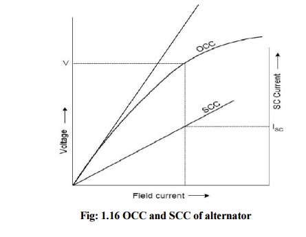
As the terminals of the stator are short circuited in SC test, the short circuit current is circulated against the impedance of the stator called the synchronous impedance. This impedance can be estimated form the oc and sc characteristics.
The ratio of open circuit voltage to the short circuit current at a particular field current, or at a field current responsible for circulating the rated current is called the synchronous impedance.
Synchronous impedance Zs = (open circuit voltage per phase)/(short circuit current per phase) for same If
Hence Zs = (Voc) / (Isc) for same If
From Fig: 1.16 synchronous impedance Zs = V/Isc
Armature resistance Ra of the stator can be measured using Voltmeter - Ammeter method. Using synchronous impedance and armature resistance synchronous reactance and hence regulation can be calculated as follows using emf method.
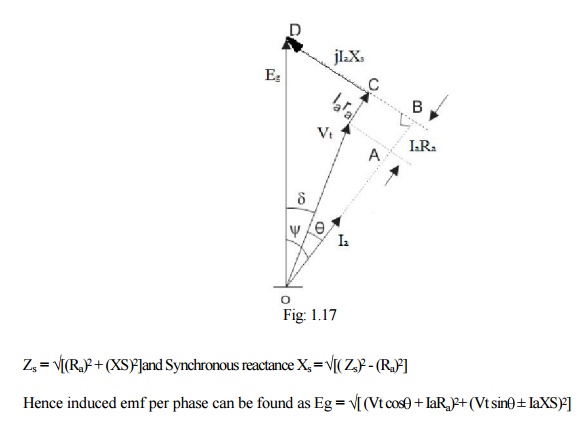
where Vt = phase voltage per phase = Vph , Ia = load current per phase
In the above expression in second term + sign is for lagging power factor and - sign is for leading power factor.
% Regulation = [ Eg – Vt ] / Vt
where
Eg = no-load induced emf /phase,
Vt = rated terminal voltage/phase
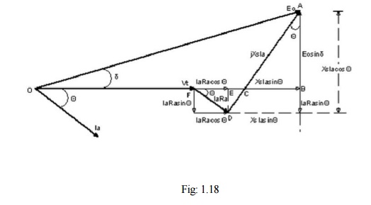
Synchronous impedance method is easy but it gives approximate results. This method gives the value of regulation which is greater (poor) than the actual value and hence this method is called pessimistic method. The complete phasor diagram for the emf method is shown in Fig 1.18.
2. MMF method
This method is also known as amp - turns method. In this method the all the emfs produced by rotor and stator are replaced by their equivalent MMFs (fluxes), and hence called mmf method. In this method also it is assumed that the magnetic circuit is unsaturated. In this method both the reactance drops are replaced by their equivalent mmfs. Fig: 1.19 shows the complete phasor diagram for the mmf method. Similar to emf method OC and SC characteristics are used for the determination of regulation by mmf method. The details are shown in Fig: 1.19. Using the details it is possible determine the regulation at different power factors.
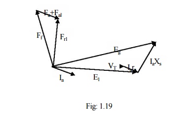
From the phasor diagram it can be seen that the mmf required to produce the emf E1= (V + IRa) is FR1.In large machines resistance drop may neglected. The mmf required to overcome the reactance drops is (Fa+Fal) as shown in phasor diagram. The mmf (Fa+Fal) can be found from SC characteristic as under SC condition both reactance drops will be present.
Following procedure can be used for determination of regulation by mmf method.
Because of the assumption of unsaturated magnetic circuit the regulation computed by this method will be less than the actual and hence this method of regulation is called optimistic method.
3. ASA Modified MMF Method:
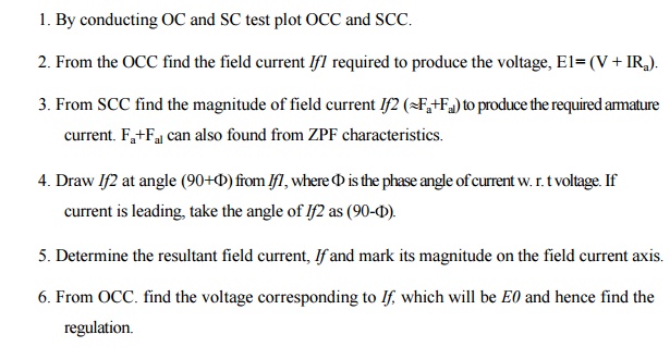
ASA or modified mmf method consider saturation effect for calculation of regulation. In the mmf method the total mmf F computed is based on the assumption of unsaturated magnetic circuit which is unrealistic. In order to account for the partial saturation of the magnetic circuit it must be increased by a certain amount FF2 which can be computed from occ, scc and air gap lines as explained below referring to Fig: 1.20 (i) and (ii).
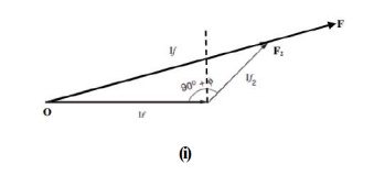
If1 is the field current required to induce the rated voltage on open circuit. Draw If2 with length equal to field current required to circulate rated current during short circuit condition at an angle (90+ ) from If1. The resultant of If1 and If2 gives If (OF2 in figure). Extend OF2 upto F so that F2F accounts for the additional field current required for accounting the effect of partial saturation of magnetic circuit. F2F is found for voltage E (refer to phasor diagram of mmf method) as shown in Fig: 1.20. Project total field current OF to the field current axis and find corresponding voltage E0 using OCC. Hence regulation can found by ASA method which is more realistic.
4. Zero Power Factor (ZPF) method or Potier Triangle Method:
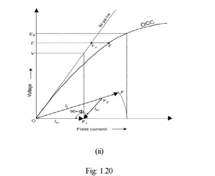
During the operation of the alternator, resistance voltage drop IaRa and armature leakage reactance drop IaXL are actually emf quantities and the armature reaction reactance is a mmf quantity. To determine the regulation of the alternator by this method OCC, SCC and ZPF test details and characteristics are required. AS explained earlier oc and sc tests are conducted and OCC and SCC are drawn. ZPF test is conducted by connecting the alternator to ZPF load and exciting the alternator in such way that the alternator supplies the rated current at rated voltage running at rated speed. To plot ZPF characteristics only two points are required. One point is corresponding to the zero voltage and rated current that can be obtained from scc and the other at rated voltage and rated current under zpf load. This zero power factor curve appears like OCC but shifted by a factor IaXL vertically and horizontally by armature reaction mmf as shown below in Fig: 1.21. Following are the steps to draw ZPF characteristics.
By suitable tests plot OCC and SCC. Draw air gap line. Conduct ZPF test at full load for rated voltage and fix the point B. Draw the line BH with length equal to field current required to produce full load current on short circuit. Draw HD parallel to the air gap line so as to cut the OCC. Draw DE perpendicular to HB or parallel to voltage axis. Now, DE represents voltage drop IXL and BE represents the field current required to overcome the effect of armature reaction.
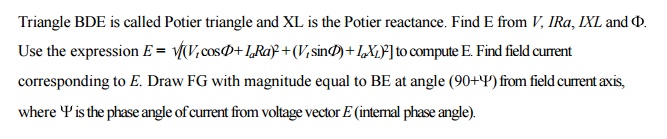
The resultant field current is given by OG. Mark this length on field current axis. From OCC find the corresponding E0. Find the regulation.
Related Topics