Chapter: Mechanical : Metrology and Measurements : Thread Measurement
Surface Finish Measurement
Introduction
When we are producing components by various methods of manufacturing process it is not possible to produce perfectly smooth surface and some irregularities are formed. These irregularities are causes some serious difficulties in using the components. So it is very important to correct the surfaces before use. The factors which are affecting surface roughness are
1. Work piece material
2. Vibrations
3. Machining type
4. Tool and fixtures
The geometrical irregularities can be classified as
1. First order
2. Second order
3 Third order
4. Fourth order
1. First order irregularities
These are caused by lack of straightness of guide ways on which tool must move.
2. Second order irregularities
These are caused by vibrations
3. Third order irregularities
These are caused by machining.
4. Fourth order irregularities
These are caused by improper handling machines and equipments.
Elements of surface texture
1. Profile: - Contour of any section through a surface.
2. Lay: - Direction of the ‘predominate surface
3. Flaws: - Surface irregularities or imperfection, which occur at infrequent intervals.
4. Actual surface: - Surface of a part which is actually obtained,
5. Roughness: - Finely spaced irregularities. It is also called primary texture.
6. Sampling lengths: - Length of profile necessary for the evaluation of the irregularities.
6. Waviness: - Surface irregularities which are of greater spacing than roughness.
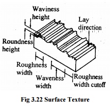
7. Roughness height: - Rated as the arithmetical average deviation.
9. Roughness width: - Distance parallel to the normal surface between successive peaks.
10. Mean line of profile: - Line dividing the effective profile such that within the sampling length.
11. Centre line of profile: - Line dividing the effectiveness profile such that the areas embraced b profile above and below the line are equal.
Analysis of surface finish
The analyses of surface finish being carried out by
1. The average roughness method.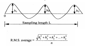
2. Peak to valley height method
3. From factor
1. Average roughness measurement
The assessment of average roughness is carried out by
a Centre line average (CLA).
b Root mean square (RMS)
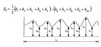
c Ten point method
a. C.L.A. method
The surface roughness is measured as the average deviation from the nominal surface.
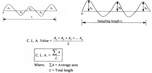
b. R.M.S. method
The roughness is measured as the average deviation from the nominal surface. Let, h1,h2, ... are the heights of the ordinates and L is the sampling length
c. Ten point height method
The average difference between five highest peaks and five lowest valleys of surface is taken and irregularities are calculated by
2. Peak to valley height method
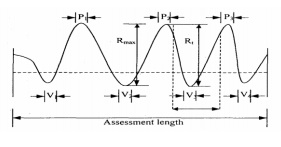
Peak to valley height measures the maximum depth of the surface irregularities over a given sample length and largest value of the depth is accepted for the measurement.
Here, = Maximum peak to valley height in one sampling lengths. R = Maximum peak to valley height
V=Valley
P = Peak
Here, R is the maximum peak to valley height within the assessment length and the disadvantages of R, and is only a single peak or valley which gives the value is not a true picture of the actual profile of the surface
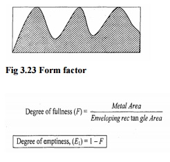
3. Form factor
It is obtained by measuring the area of material above the arbitrarily chosen base line in the section and the area of the enveloping rectangle.
Methods of measuring surface finish
The methods used for measuring the surface finish is classified into
1. Inspection by comparison
2. Direct Instrument Measurements
1. Inspection by comparison methods:
In these methods the surface texture is assessed by observation of the surface. The surface to be tested is compared with known value of roughness specimen and finished by similar machining process.
The various methods which are used for comparison are
1. Touch Inspection.
2. Visual Inspection.
3. Microscopic Inspection.
4. Scratch Inspection.
5. Micro Interferometer.
6. Surface photographs.
7. Reflected Light Intensity.
8. Wallace surface Dynamometer.
· Touch Inspection
It is used when surface roughness is very high and in this method the fingertip is moved along the surface at a speed of 25mm/second and the irregularities as up to 0.0125mm can be detected.
· Visual Inspection
In this method the surface is inspected by naked eye and this measurement is limited to rough surfaces.
· Microscopic Inspection
In this method finished surface is placed under the microscopic and compared with the surface under inspection. The light beam also used to check the finished surface by projecting the light about 60° to the work.
· Scratch Inspection:
The materials like lead, plastics rubbed on surface are inspected by this method. The impression of this scratches on the surface produced is then visualized.
· Micro-Interferometer
Optical flat is placed on the surface to be inspected and illuminated by a monochromatic source of light.
· Surface Photographs
Magnified photographs of the surface are taken with different types of illumination. The defects like irregularities are appear as dark spots and flat portion of the surface appears as bright.
· Reflected light Intensity
A beam of light is projected on the surface to be inspected and the light intensity variation on the surface is measured by a photocell and this measured value is calibrated
· Wallace surface Dynamometer:
It consists of a pendulum in which the testing shoes are clamped to a bearing surface and a pre determined spring pressure can be applied and then, The pendulum is lifted to its initial starting position and allowed to swing over the surface to be tested.
2. Direct instrument measurements
Direct methods enable to determine a numerical value of the surface finish of any surface. These methods are quantitative analysis methods and the output is used to operate recording or indicating instrument. Direct Instruments are operated by electrical principles. These instruments are classified into two types according to the operating principle. In this is operated by carrier-modulating principle and the other is operated by voltage-generating principle, and in the both types the output is amplified.
Some of the direct measurement instruments are
1. Stylus probe instruments.
2. Tomlinson surface meter.
3. Profilometer.
4. Taylor-Hobson Talysurf
1. Stylus probe type instrument
Principle
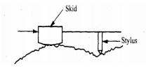
When the stylus is moved over the surface which is to be measured, the irregularities in the surface texture are measured and it is used to assess the surface finish of the work piece.
Working
The stylus type instruments consist of skid, stylus, amplifying device and recording device. The skid is slowly moved over the surface by hand or by motor drive. The skid follows the irregularities of the surface and the stylus moves along with skid. When the stylus moves vertically up and down and the stylus movements are magnified, amplified and recorded to produce a trace. Then it is analyzed by automatic device.
Advantage
Any desired roughness parameter can be recorded.
Disadvantages
1. Fragile material cannot be measured.
2. High Initial cost.
3. Skilled operators are needed to operate.
2. Tomlinson Surface meter
This instrument uses mechanical-cum-optical means for magnification.
Construction
In this the diamond stylus on the surface finish recorder is held by spring pressure against the surface of a lapped cylinder. The lapped cylinder is supported one side by probe and other side by rollers. The stylus is also attached to the body of the instrument by a leaf spring and its height is adjustable to enable the diamond to be positioned and the light spring steel arm is attached to the lapped cylinder. The spring arm has a diamond scriber at the end and smoked glass is rest on the arm.
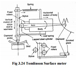
When measuring surface finish the body of the instrument is moved across the surface by a screw rotation. The vertical movement of the probe caused by the surface irregularities makes the horizontal lapped cylinder to roll. This rolling of lapped cylinder causes the movement of the arm. So this movement is induces the diamond scriber on smoked glass. Finally the movement of scriber together with horizontal movement produces a trace on the smoked glass plate and this trace is
magnified by an optical projector.
3. Profilometer
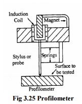
It is an indicating and recording instrument to measure roughness in microns. The main parts of the instrument are tracer and an amplifier. The stylus is mounted in the pickup and it consists of induction oil located in the magnet. When the stylus is moved on the surface to be tested, it is displaced up and down due to irregularities in the surface. This movement induces the induction coil to move in the direction of permanent magnet and produces a voltage. This is amplified and recorded.
4. Talyor-Hobson-Talysurf
It is working a carrier modulating principle and it is an accurate method comparing with the other methods. The main parts of this instrument is diamond stylus (0.002mm radius) and skid
Principle
The irregularities of the surface are traced by the stylus and the movement of the stylus is converted into changes in electric current.
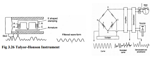
Fig 3.26 Talyor-Honson Instrument
Working
On two legs of the E-shaped stamping there are coils for carrying an A.C. current and these coils form an oscillator. As the armature is pivoted about the central leg the movement of the stylus causes the air gap to vary and thus the amplitude is modulated. This modulation is again demodulated for the vertical displacement of the stylus. So this demodulated output is move the pen recorder to produce a numerical record and to make a direct numerical assessment.
Related Topics