Chapter: Mechanical : Metrology and Measurements : Thread Measurement
Flatness Testing
FLATNESS TESTING
Flatness testing is possible by
comparing the surface with an accurate surface. This method is suitable for
small plates and not for large surfaces. Mathematically flatness error of a
surface states that the departure from flatness is the minimum separation of a
pair of parallel planes which will contain all points on the Surface. The
figure which shows that a surface can be considered to be composed of an
infinitely large number of lines. The surface will be flat only if all the
lines are straight and they lie in the same plane. In the case of rectangular
table arc the lines are straight and parallel to the sides of the rectangle in
both the perpendicular direction. Even it is not plat, but concave and convex along
two diagonals. For verification, it is essential to measure the straightness of
diagonals in addition to the lines parallel to the sides.
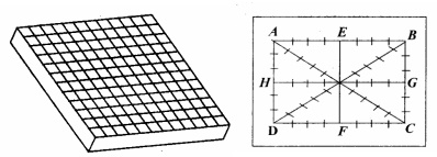
Thus the whole of the surface is divided
by straight line. The fig, shows the surface is divided by straight line. The
end line AB and AD etc are drawn away from the edges as the edges of the
surface are not flat but get worn out by use and can fall off little in
accuracy. The straightness of all these lines is determined and then those
lines are related with each other in order to verify whether they lie in the same plane or not.
Procedure for
determining flatness
The
fig. shows the flatness testing procedure.
(i)
Carry out the straightness test and
tabulate the reading up to the cumulative error column.
(ii)
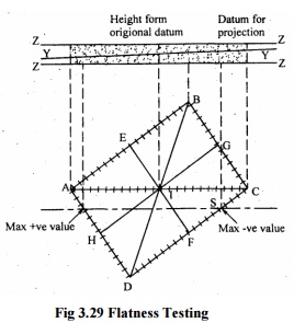
Ends of lines AB, AD and BD are
corrected to zero and thus the height of the points A, B and D are zero.

Fig
3.29 Flatness Testing
The height of the point I is determined
relative to the arbitrary plane ABD = 000. Point C is now fixed relative to the
arbitrary plane and points B and D are set at zero, all intermediate points on
BC and DC can be corrected accordingly. The positions of H and G, E and F are
known, so it is now possible to fit in lines HG and EF. This also provides a
check on previous evaluations since the mid-point of these lines should
coincide with the position of mid-point I. In this way, the height of all the
points on the surface relative to the arbitrary plane ABD is known.
Related Topics