Chapter: Mechanical : Metrology and Measurements : Thread Measurement
Roundness Measurement
ROUNDNESS MEASUREMENTS
Roundness is defined as a condition of a
surface of revolution. Where all points of the surface intersected by any plane
perpendicular to a common axis in case of cylinder and cone.
Devices used for
measurement of roundness
1) Diametral
gauge.
2) Circumferential
conferring gauge => a shaft is confined in a ring gauge and rotated against
a set indicator probe.
3) Rotating
on center
4) V-Block
5) Three-point
probe.
6) Accurate
spindle.
1.
Diametral method
The measuring plungers are located 180°
a part and the diameter is measured at several places. This method is suitable
only when the specimen is elliptical or has an even number of lobes. Diametral
check does not necessarily disclose effective size or roundness. This method is
unreliable in determining roundness.
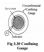
1. Circumferential
confining gauge
Fig.
shows the principle of this method. It is useful for inspection of roundness in
production. This method requires highly accurate master for each size part to
be measured. The clearance between part and gauge is critical to reliability.
This technique does not allow for the measurement of other related geometric
characteristics, such as concentricity, flatness of shoulders etc.
3. Rotating on centers
The
shaft is inspected for roundness while mounted on center. In this case,
reliability is dependent on many factors like angle of centers, alignment of
centres, roundness and surface condition of the centres and centre holes and
run out of piece. Out of straightness of the part will cause a doubling run out
effect and appear to be roundness error.
2. V-Block
The
set up employed for assessing the circularity error by using V Block is shown
in fig.
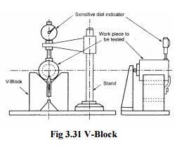
The
V block is placed on surface plate and the work to be checked is placed upon
it. A diameter indicator is fixed in a stand and its feeler made to rest
against the surface of the work. The work is rotated to measure the rise on
fall of the workpiece. For determining the number of lobes on the work piece,
the work piece is first tested in a 60° V-Block and then in a 90° V-Block. The
number of lobes is then equal to the number of times the indicator pointer
deflects through 360° rotation of the work piece.
Limitations
a)
The circularity error is greatly by affected by the following factors.
(i) If
the circularity error is i\e, then it is possible that the indicator shows no
variation.
(ii) Position
of the instrument i.e. whether measured from top or bottom.
(iii) Number
of lobes on the rotating part.
b) The
instrument position should be in the same vertical plane as the point of
contact of the part with the V-block.
c) A
leaf spring should always be kept below the indicator plunger and the surface
of the part.
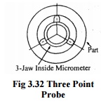
5.
Three point probe
The
fig. shows three probes with 120° spacing is very, useful for determining
effective size they perform like a 60° V-block. 60° V-block will show no error
for 5 a 7 lobes magnify the error for 3-lobed parts show partial error for
randomly spaced lobes.
Roundness measuring
spindle
There are following two types of spindles used.
1.Overhead spindle
Part is fixed in a staging plat form and
the overhead spindle carrying the comparator rotates separately from the part.
It can determine roundness as well as camming (Circular flatness). Height of
the work piece is limited by the location of overhead spindle. The
concentricity can be checked by extending the indicator from the spindle and
thus the range of this check is limited.
2.Rotating table
Spindle is integral with the table and rotates along
with it. The part is placed over the spindle and rotates past a fixed
comparator
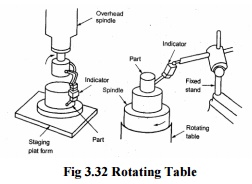
Fig 3.32 Rotating Table
Roundness measuring
machine
Roundness is the property of a surface of revolution,
where all points on the surface are equidistant from the axis. The roundness of
any profile can be specified only when same center is found from which to make
the measurements. The diameter and roundness are measured by different method
and instruments. For measurement of diameter it is done statically, for
measuring roundness, rotation is always necessary. Roundness measuring
instruments are two types.
1. Rotating
pick up type.
2. Turn
table type.
These are accurate, speed and reliable
measurements. The rotating pick up type the work piece is stationary and the
pickup revolved. In the turn table the work piece is rotated and pick up is
stationery. On the rotating type, spindle is designed to carry the light load
of the pickup. The weight of the work piece, being stationary and is easy to
make. In the turn table type the pickup is not associated with the spindle.
This is easier to measure roundness. Reposition the pickup has no effects on
the reference axis.
The pickup converts the circuit movement
of the stylus into electrical signal, which is processed and amplified and fed
to a polar recorder. A microcomputer is incorporated with integral visual
display unit and system is controlled from compact keyboards, which increases
the system versatility, scope and speed of analysis. System is programmed to
access the roundness of work piece with respect to any four of the
internationality recognized reference circles. A visual display of work piece
profile can be obtained. Work piece can be assessed over a circumference, and
with undercut surface or an interrupted surface with sufficient data the
reference circle can be fitted to the profile. The program also provides
functions like auto centering, auto ranging, auto calibration and
concentricity.
Modern Roundness
Measuring Instruments
This is based on use of microprocessor to provide
measurements of roundness quickly and in a simple way; there is no need of
assessing out of roundness. Machine can do centering automatically and
calculate roundness and concentricity, straightness and provide visual and
digital displays. A computer is used to speed up calculations and provide the
stand reference circle.
(i) Least square circle
The sum of the squares
of a sufficient no. of equally spaced radial ordinates measured from the circle
to the profile has minimum value. The center of such circle is referred to as
the least square center. Out of roundness is defined as the radial distance of
the maximum peak from the circle (P) plus the distance of the maximum valley
from this circle.
(ii) Minimum zone or Minimum radial
separation circle
These are two
concentric circles. The value of the out of roundness is the radial distance
between the two circles. The center of such a circle is termed as the minimum
zone center. These circles can be found by using a template.
(iii) Maximum inscribed circle
This is the largest
circle. Its center and radius can be found by trial and error by compare or by
template or computer. Since V = 0 there is no valleys inside the circle.
(iv)Minimum circumscribed circles
This is the smallest
circle. Its center and radius can be found by the previous method since P = 0
there is no peak outside the circle. The radial distance between the minimum
circumscribing circle and the maximum inscribing circle is the measure of the
error circularity. The fig shows the trace produced by a recording instrument.
This trace to draw concentric circles on the polar
graph which pass through the maximum and minimum points in such way that the
radial distance be minimum circumscribing circle containing the trace or the n
inscribing circle which can fitted into the trace is minimum. The radial
distance between the outer and inner circle is minimum is considered for
determining the circularity error. Assessment of roundness can be done by
templates. The out off roundness is defined as the radial distance of the
maximum peak (P) from the least square circle plus the distance of the maximum
valley (V) from the least square circle. All roundness analysis can be
performed by harmonic and slope analysis.
Related Topics