Chapter: Computer Networks : Data Link Layer
Standard Ethernet
Standard Ethernet
The
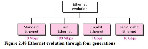
original Ethernet was created in 1976 at Xerox's Palo Alto Research Center
(PARC). Since then, it has gone through four generations:
a.
Standard Ethernet (l0 Mbps),
b. Fast
Ethernet (100 Mbps),
c.
Gigabit Ethernet (l Gbps)
d.
Ten-Gigabit Ethernet (l0 Gbps)
MAC Sublayer
In
Standard Ethernet, the MAC sublayer governs the operation of the access method.
It also frames data received from the upper layer and passes them to the
physical layer.
1. Frame Format
The
Ethernet frame contains seven fields: preamble, SFD, DA, SA, length or type of
protocol data unit (PDU), upper-layer data, and the CRC. Ethernet does not
provide any mechanism for acknowledging received frames, making it what is
known as an unreliable medium. Acknowledgments must be implemented at the
higher layers.
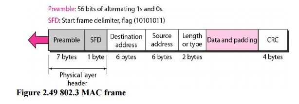
Preamble: The first field of the 802.3
frame contains 7 bytes (56 bits) of alternating 0sand 1s that alerts the
receiving system to the coming frame and enables it to synchronize its input
timing. The pattern provides only an alert and a timing pulse.
Start frame delimiter (SFD). The
second field (l byte: 10101011) signals the beginningof the frame. The SFD
warns the station or stations that this is the last chance for synchronization.
The last 2 bits is 11 and alerts the receiver that the next field is the
destination address.
Destination address (DA). The DA
field is 6 bytes and contains the physical address ofthe destination station or
stations to receive the packet.
Source address (SA). The SA
field is also 6 bytes and contains the physical address ofthe sender of the
packet.
Length or type. This field is defined as a type
field or length field. The original Ethernetused this field as the type field
to define the upper-layer protocol using the MAC frame.
Data. This field carries data
encapsulated from the upper-layer protocols. It is aminimum of 46 and a maximum
of 1500 bytes.
CRC. The last field contains error
detection information, in this case a CRC-32.
2. Frame Length
Ethernet
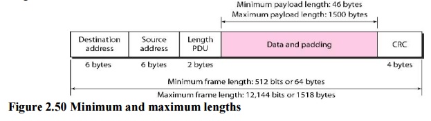
has imposed restrictions on both the minimum and maximum lengths of a frame. An
Ethernet frame needs to have a minimum length of 512 bits or 64 bytes. Part of
this length is the header and the trailer. If we count 18 bytes of header and
trailer, then the minimum length of data from the upper layer is 64 - 18 = 46
bytes. If the upper-layer packet is less than 46 bytes, padding is added to
make up the difference.
The
standard defines the maximum length of a frame as 1518 bytes. If we subtract
the 18 bytes of header and trailer, the maximum length of the payload is 1500
bytes. The maximum length restriction has two historical reasons.
3. Addressing
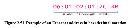
Each
station on an Ethernet network has its own network interface card (NIC). The
NIC fits inside the station and provides the station with a 6-byte physical
address. The Ethernet address is 6 bytes (48 bits), nominally written in
hexadecimal notation, with a colon between the bytes.
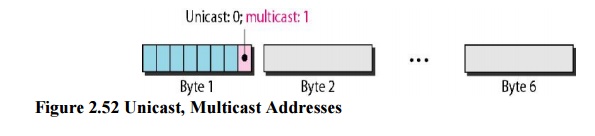
Unicast, Multicast, and Broadcast Addresses:
A source
address is always a unicast address-the frame comes from only one station. The
destination address, however, can be unicast, multicas
t, or
broadcast. If the least significant bit of the first byte in a destination
address is 0, the address is unicast; otherwise, it is multicast. The broadcast
address is a special case of the multicast address; the recipients are all the
stations on the LAN. A broadcast destination address is forty-eight 1s.
Example 2.13
Define the type of the following destination addresses:
a. 4A:30:10:21:1O:1A
b. 47:20:1B:2E:08:EE
c. FF:FF:FF:FF:FF:FF
Solution
To find
the type of the address, we need to look at the second hexadecimal digit from
the left. If it is even, the address is unicast. If it is odd, the address is
multicast. If all digits are F's, the address is broadcast. Therefore, we have
the following:
· This is a
unicast address because A in binary is 1010 (even).
· This is a
multicast address because 7 in binary is 0111 (odd).
·
This is a broadcast address because all digits are
F's
Example 13.2
Show how
the address 47:20:1B:2E:08:EE is sent out on line.
Solution
The
address is sent left-to-right, byte by byte; for each byte, it is sent
right-to-left, bit by bit, as shown below:

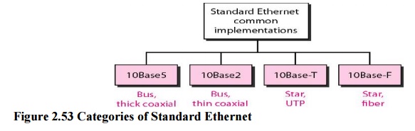
4. Physical layer
The
Standard Ethernet defines several physical layer implementations; four of the
most Common.
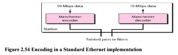
Encoding and Decoding
All
standard implementations use digital signaling (baseband) at 10 Mbps. At the
sender, data are converted to a digital signal using the Manchester scheme; at
the receiver, the received signal is interpreted as Manchester and decoded into
data. Manchester encoding is self-synchronous, providing a transition at each
bit interval. Figure 2.60 shows the encoding scheme for Standard Ethernet
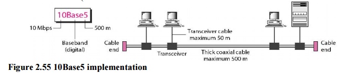
a. 10Base5: Thick Ethernet
The first
implementation is called 10Base5, thick Ethernet, or Thicknet. The nickname derives
from the size of the cable, which is roughly the size of a garden hose and too
stiff to bend with your hands. 10Base5 was the first Ethernet specification to
use a bus topology with an external transceiver (transmitter/receiver)
connected via a tap to a thick coaxial cable
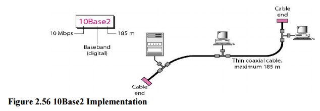
b. 10Base2: Thin Ethernet
The
second implementation is called 10Base2, thin Ethernet, or Cheapernet. 10Base2
also uses a bus topology, but the cable is much thinner and more flexible. The
cable can be bent to pass very close to the stations. In this case, the
transceiver is normally part of the network interface card (NIC), which is
installed inside the station.
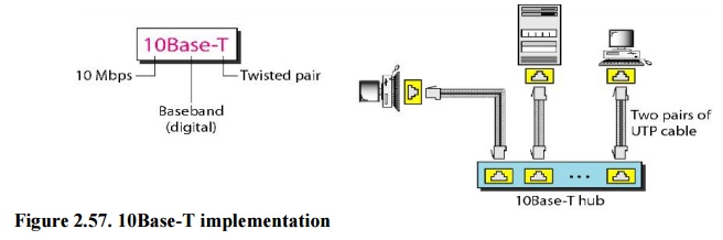
c. 10Base-T: Twisted-Pair Ethernet
The third
implementation is called 10Base-T or twisted-pair Ethernet. 10Base-T uses a
physical star topology. The stations are connected to a hub via two pairs of
twisted cable.
Note that
two pairs of twisted cable create two paths between the station and the hub.
Any collision here happens in the hub. Compared to 10Base5 or 10Base2, we can
see that the hub actually replaces the coaxial cable as far as a collision is
concerned. The maximum length of the twisted cable here is defined as 100 m, to
minimize the effect of attenuation in the twisted cable.
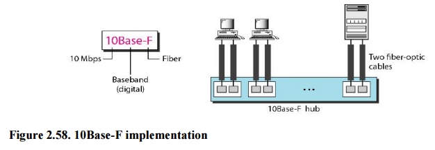
d. 10Base-F: Fiber Ethernet
Although
there are several types of optical fiber 10-Mbps Ethernet, the most common is
called 10Base-F. 10Base-F uses a star topology to connect stations to a hub.
The stations are connected to the hub using two fiber-optic cables
Related Topics