Chapter: Computer Networks : Data Link Layer
Random Access
Random Access:
In random
access or contention methods, no station is superior to another station and
none is assigned the control over another. No station permits, or does not
permit, another station to send. At each instance, a station that has data to
send uses a procedure defined by the protocol to make a decision on whether or
not to send. This decision depends on the state of the medium (idle or busy).
In other words, each station can transmit when it desires on the condition that
it follows the predefined procedure, including the testing of the state of the
medium.
Two features give this method its name.
First,
there is no scheduled time for a station to transmit. Transmission is random
among the stations. That is why these methods are called random access.
Second,
no rules specify which station should send next. Stations compete with one
another to access the medium. That is why these methods are also called
contention methods.
1. ALOHA
It was
designed for a radio (wireless) LAN, but it can be used on any shared medium.
It is
obvious that there are potential collisions in this arrangement. The medium is
shared between the stations. When a station sends data, another station may
attempt to do so at the same time. The data from the two stations collide and
become garbled.
2. Pure ALOHA
The
original ALOHA protocol is called pure ALOHA. This is a simple, but elegant
protocol. The idea is that each station sends a frame whenever it has a frame
to send. However, since there is only one channel to share, there is the
possibility of collision between frames from different stations.

Figure 2.31 Frames in a a pure ALOHA Network
There are
four stations (unrealistic assumption) that contend with one another for access
to the shared channel. The figure shows that each station sends two frames;
there are a total of eight frames on the shared medium. Some of these frames
collide because multiple frames are in contention for the shared channel. Frame
1.1 from station 1 and frame 3.2 from station 3. We need to mention that even
if one bit of a frame coexists on the channel with one bit from another frame,
there is a collision and both will be destroyed.
The
time-out period is equal to the maximum possible round-trip propagation delay,
which is twice the amount of time required to send a frame between the two most
widely separated stations (2 x Tp)'. The back-off time TB is a random value
that normally depends on K (the number of attempted unsuccessful
transmissions). The formula for TB depends on the implementation. One common
formula is the binary exponential back-off.
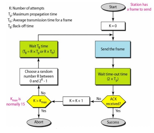
Figure 2.32 Procedure for Pure ALOHA Protocol
Example 2.8
The
stations on a wireless ALOHA network is a maximum of 600 km apart. If we assume
that signals propagate at 3 x 10⁸ mis, we find Tp = (600 x 105) / (3 x 10⁸) = 2
ms. Now we can find the value of TB for different values of K.
a. For K
= 1, the range is {0, 1}. The station needs to generate a random number with a
value of 0 or 1. This means that TB is either 0 ms (0 x 2) or 2 ms (1 x 2),
based on the outcome of the random variable.
b. For K
=2, the range is {0, 1, 2, 3}. This means that TB can be 0, 2, 4, or 6 ms,
based on the outcome of the random variable.
c. For K
=3, the range is to, 1, 2, 3, 4, 5, 6, 7}. This means that TB can be 0, 2, 4,
..., 14 ms, based on the outcome of the random variable.
d. We
need to mention that if K > 10, it is normally set to 10.
Vulnerable
time:
Let us
find the length of time, the vulnerable time, in which there is a possibility
of collision. We assume that the stations send fixed-length frames with each
frame taking Tfr S to send.
Station A
sends a frame at time t. Now imagine station B has already sent a frame between
t - Tfr and t. This leads to a collision between the frames from
station A and station B. The end of B's frame collides with the beginning of A's
frame. On the other hand, suppose that station C sends a frame between t and t
+ Tfr. Here, there is a collision between frames from station A and
station C. The beginning of C's frame collides with the end of A's frame.
During
which a collision may occur in pure ALOHA, is 2 times the frame transmission
time. Pure ALOHA vulnerable time = 2 x Tfr
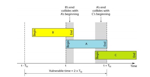
Figure 2.33 Vulnerable time for pure ALOHA Protocol
Example 2.9
A pure
ALOHA network transmits 200-bit frames on a shared channel of 200 kbps. What is
the requirement to make this frame collision-free?
Solution
Average
frame transmission time Tfr is 200 bits/200 kbps or 1 ms.The
vulnerable time is 2 x 1 ms =2 ms. This means no station should send later than
1 ms before this station starts transmission and no station should start
sending during the one I-ms period that this station is sending.
Throughput
Let us
call G the average number of frames generated by the system during one frame
transmission time. Then it can be proved that the average number of successful
transmissions for pure ALOHA is S = G x e-2G. The maximum throughput
Smax is 0.184, for G = 1. Therefore, if a station generates only one frame in
this vulnerable time (and no other stations generate a frame during this time),
the frame will reach its destination successfully.
Example 2.10
A pure
ALOHA network transmits 200-bit frames on a shared channel of 200 kbps. What is
the throughput if the system (all stations together) produces?
· 1000
frames per second
· 500
frames per second
· 250
frames per second
Solution
The frame
transmission time is 2001200 kbps or 1 ms.
a)
If the system creates 1000 frames per second, this
is 1 frame per millisecond. The load is 1. In this case S =G x e-2G
or S =0.135 (13.5 percent). This means that the throughput is 1000 X 0.135 =135
frames. Only 135 frames out of 1000 will probably survive.
b) If the
system creates 500 frames per second, this is (1/2) frame per millisecond. The
load is (112). In this case S = G x e-2G or S = 0.184 (18.4
percent). This means that the throughput is 500 x 0.184 =92 and that only 92
frames out of 500 will probably survive. Note that this is the maximum
throughput case, percentagewise.
c)
If the system creates 250 frames per second, this
is (1/4) frame per millisecond. The load is (1/4). In this case S = G x e-2G
or S =0.152 (15.2 percent). This means that the throughput is 250 x 0.152 = 38.
Only 38 frames out of 250 will probably survive.
3. Slotted ALOHA
Pure
ALOHA has a vulnerable time of 2 x Tfr . This is so because there is
no rule that defines when the station can send. A station may send soon after
another station has started or soon before another station has finished.
Slotted ALOHA was invented to improve the efficiency of pure ALOHA.
In
slotted ALOHA we divide the time into slots of Tfr s and force the
station to send only at the beginning of the time slot.
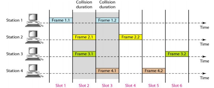
Figure 2.34 Frames in a slotted ALOHA Network
Throughput:
It can be
proved that the average number of successful transmissions for slotted ALOHA is
S = G x e-G. The maximum throughput Smax is 0.368, when G = 1.
Therefore, if a station generates only one frame in this vulnerable time (and
no other station generates a frame during this time), the frame will reach its
destination successfully.
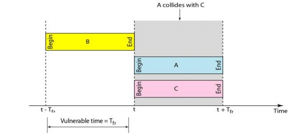
Figure 2.35 Vulnerable time for slotted ALOHA
protocol
Example 2.11
A slotted
ALOHA network transmits 200-bit frames using a shared channel with a 200-kbps
bandwidth. Find the throughput if the system (all stations together) produces
a)1000
frames per second
b)500
frames per second
c)
250 frames per second
Solution
This
situation is similar to the previous exercise except that the network is using
slotted ALOHA instead of pure ALOHA. The frame transmission time is 200/200
kbps or 1 ms.
a)
In this case G is 1. So S =G x e-G or S
=0.368 (36.8 percent). This means that the throughput is 1000 x 0.0368 =368
frames. Only 368 out of 1000 frames will probably survive. Note that this is
the maximum throughput case, percentagewise.
b) Here G is
1/2. In this case S =G x e-G or S =0.303 (30.3 percent). This means
that the throughput is 500 x 0.0303 =151. Only 151 frames out of 500 will
probably survive.
c)
Now G is 1. In this case S =G x e-G or S
=0.195 (19.5 percent). This means that the throughput is 250 x 0.195 = 49. Only
49 frames out of 250 will probably survive.
4. Carrier Sense Multiple Access
(CSMA)
To
minimize the chance of collision and, therefore, increase the performance, the
CSMA method was developed. The chance of collision can be reduced if a station
senses the medium before trying to use it. Carrier sense multiple access (CSMA)
requires that each station first listen to the medium (or check the state of
the medium) before sending.
The
possibility of collision still exists because of propagation delay; when a
station sends a frame, it still takes time (although very short) for the first
bit to reach every station and for every station to sense it. In other words, a
station may sense the medium and find it idle, only because the first bit sent
by another station has not yet been received.
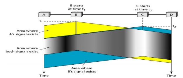
Figure 2.36 Space/time model of the collision in
CSMA
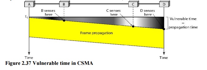
Vulnerable
Time
The
vulnerable time for CSMA is the propagation time Tp. This is the
time needed for a signal to propagate from one end of the medium to the other.
When a station sends a frame, and any other station tries to send a frame
during this time, a collision will result.
But if
the first bit of the frame reaches the end of the medium, every station will
already have heard the bit and will refrain from sending. The leftmost station
A sends a frame at time tl' which reaches the rightmost station D at
time tl + Tp. The gray area shows the vulnerable area in
time and space.
Persistence
Methods:
Three
methods have been devised to answer these questions: the I-persistent method,
the nonpersistent method, and the p-persistent method.
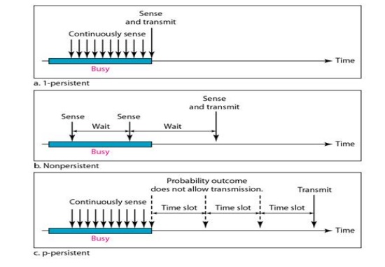
Figure 2.38 Behavior Of Three Persistence Methods
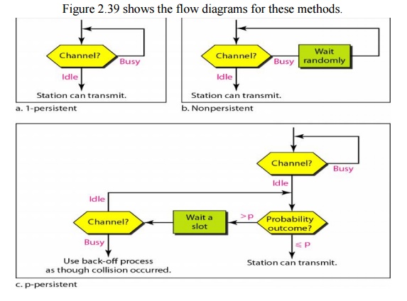
Figure 2.39 Flow diagram for three persistence
methods.
5. Carrier Sense Multiple Access
with Collision Detection (CSMA/CD)
The CSMA
method does not specify the procedure following a collision. Carrier sense
multiple access with collision detection (CSMA/CD) augments the algorithm to
handle the collision. In this method, a station monitors the medium after it
sends a frame to see if the transmission was successful. If so, the station is
finished. If, however, there is a collision, the frame is sent again.
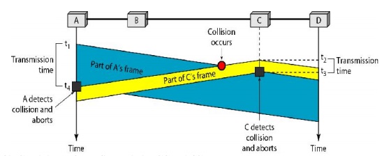
Figure 2.40 Collision of the first bit in CSMA/CD
Example 2.12
A network
using CSMA/CD has a bandwidth of 10 Mbps. If the maximum propagation time
(including the delays in the devices and ignoring the time needed to send a
jamming signal) is 25.611S, what is the minimum size of the frame?
Solution
The frame
transmission time is Tfr = 2 x Tp =51.2 µ s. This means,
in the worst case, a station needs to transmit for a period of 51.2 ~s to
detect the collision. The minimum size of the frame is 10 Mbps x 51.2 µ s =512
bits or 64 bytes. This is actually the minimum size of the frame for Standard
Ethernet.
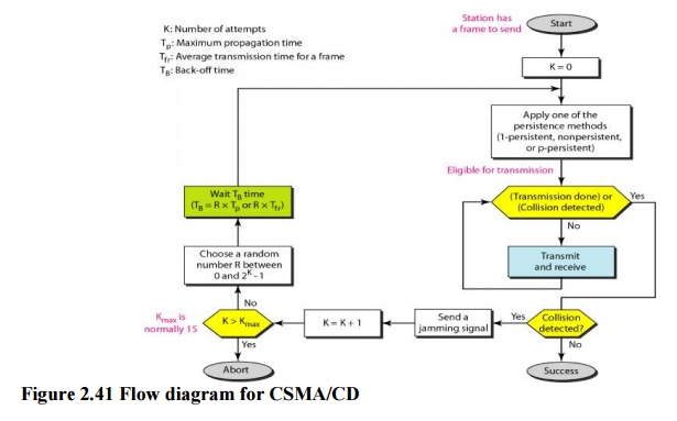
Figure
2.41 shows the flow diagram for CSMA/CD
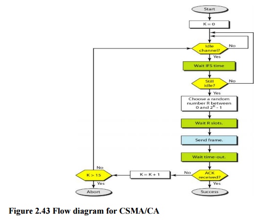
6. Carrier Sense Multiple Access with Collision Avoidance (CSMA/CA)
In a
wired network, the received signal has almost the same energy as the sent
signal because either the length of the cable is short or there are repeaters
that amplify the energy between the sender and the receiver. This means that in
a collision, the detected energy almost doubles. However, in a wireless
network, much of the sent energy is lost in transmission. The received signal
has very little energy. Therefore, a collision may add only 5 to 10 percent
additional energy. This is not useful for effective collision detection. We
need to avoid collisions on wireless networks because they cannot be detected.
Carrier sense multiple access with collision avoidance (CSMA/CA) was invented
for this network. Collisions are avoided through the use of CSMA/CA's three
strategies: the interframe space, the contention window, and acknowledgments.
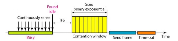
Figure 2.42 Timing in CSMA/CA
Note that
the channel needs to be sensed before and after the IFS. The channel also needs
to be sensed during the contention time. For each time slot of the contention
window, the channel is sensed. If it is found idle, the timer continues; if the
channel is found busy, the timer is stopped and continues after the timer
becomes idle again.
Interframe
Space (IFS)
First,
collisions are avoided by deferring transmission even if the channel is found
idle. When an idle channel is found, the station does not send immediately. It
waits for a period of time called the interframe space or IFS. Even though the
channel may appear idle when it is sensed, a distant station may have already
started transmitting. The distant station's signal has not yet reached this
station.
Contention
Window
The
contention window is an amount of time divided into slots. A station that is
ready to send chooses a random number of slots as its wait time. The number of
slots in the window changes according to the binary exponential back-off
strategy. This means that it is set to one slot the first time and then doubles
each time the station cannot detect an idle channel after the IFS time.
Acknowledgment
With all
these precautions, there still may be a collision resulting in destroyed data.
In addition, the data may be corrupted during the transmission. The positive
acknowledgment and the time-out timer can help guarantee that the receiver has
received the frame.
CSMA/CA and Wireless Networks
CSMA/CA
was mostly intended for use in wireless networks. The procedure described
above, however, is not sophisticated enough to handle some particular issues
related to wireless networks, such as hidden terminals or exposed terminals.
Related Topics