Chapter: Computer Networks : Data Link Layer
IEEE 802.11
Wireless LANs:
Wireless
communication is one of the fastest-growing technologies. The demand for
connecting devices without the use of cables is increasing everywhere. Wireless
LANs can be found on college campuses, in office buildings, and in many public
areas.
IEEE 802.11
IEEE has
defined the specifications for a wireless LAN, called IEEE 802.11, which covers
the physical and data link layers.
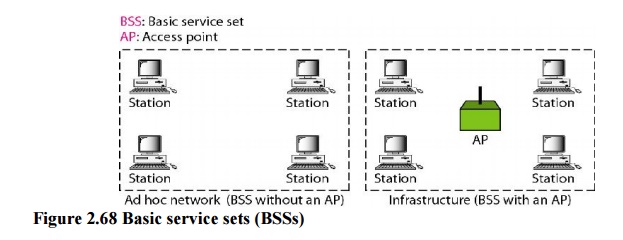
1. Architecture: The standard defines two kinds of
services: the basic service set (BSS) andthe extended service set (ESS).
Basic
Service Set
IEEE
802.11 defines the basic service set (BSS) as the building block of a wireless
LAN. A basic service set is made of stationary or mobile wireless stations and
an optional central base station, known as the access point (AP).
The BSS
without an AP is a stand-alone network and cannot send data to other BSSs. It
is called an ad hoc architecture. In this architecture, stations can form a
network without the need of an AP; they can locate one another and agree to be
part of a BSS. A BSS with an AP is sometimes referred to as an infrastructure
network
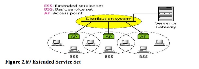
Extended
Service Set
An
extended service set (ESS) is made up of two or more BSSs with APs. In this
case, the BSSs are connected through a distribution system, which is usually a wired LAN. The distribution system connects
the APs in the BSSs. IEEE 802.11 does not restrict the distribution system; it
can be any IEEE LAN such as an Ethernet. Note that the extended service set
uses two types of stations: mobile and stationary. The mobile stations are
normal stations inside a BSS. The stationary stations are AP stations that are
part of a wired LAN.
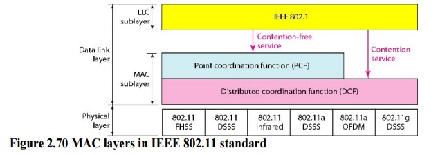
2. MAC Sublayer
IEEE
802.11 defines two MAC sublayers: the distributed coordination function (DCF)
and point coordination function (PCF). Figure 14.3 shows the relationship
between the two MAC sublayers, the LLC sublayer, and the physical layer.
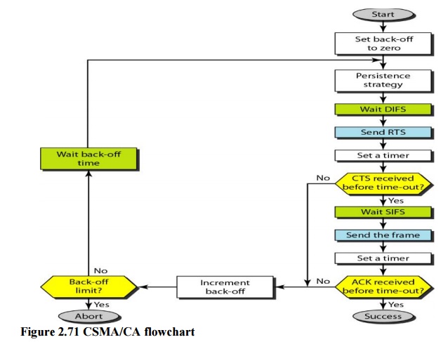
a. Distributed Coordination Function
One of
the two protocols defined by IEEE at the MAC sublayer is called the distributed
coordination function (DCF). DCF uses CSMAICA
as the access method.
Wireless
LANs cannot implement CSMA/CD for
three reasons:
1.
For collision detection a station must be able to
send data and receive collision signals at the same time. This can mean costly
stations and increased bandwidth requirements.
2.
Collision may not be detected because of the hidden
station problem.
3.
The distance between stations can be great. Signal
fading could prevent a station at one end from hearing a collision at the other
end.
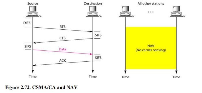
Network Allocation Vector
When a
station sends an RTS frame, it includes the duration of time that it needs to
occupy the channel. The stations that are affected by this transmission create
a timer called a network allocation vector (NAV) that shows how much time must
pass before these stations are allowed to check the channel for idleness. Each
time a station accesses the system and sends an RTS frame, other stations start
their NAV.
b. Point Coordination Function (PCP)
The point
coordination function (PCF) is an optional access method that can be
implemented in an infrastructure network (not in an ad hoc network). It is
implemented on top of the DCF and is used mostly for time-sensitive
transmission. PCF has a centralized, contention-free polling access method. The
AP performs polling for stations that are capable of being polled. The stations
are polled one after another, sending any data they have to the AP.
3. Frame Format
The MAC
layer frame consists of nine fields.
Frame control (FC): The FC
field is 2 bytes long and defines the type of frame andsome control
information.
D. In all frame types except one,
this field defines the duration of the transmission that isused to set the
value of NAY. In one control frame, this field defines the ID of the frame
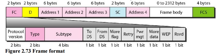
Addresses. There are four address fields,
each 6 bytes long. The meaning of each addressfield depends on the value of the
To DS and From DS subfields.
Sequence control. This field defines the sequence
number of the frame to be used inflow control.
Frame body. This field, which can be
between 0 and 2312 bytes, contains informationbased on the type and the subtype
defined in the FC field.
FCS. The FCS field is 4 bytes long
and contains a CRC-32 error detection sequence.
4. Frame Types
A
wireless LAN defined by IEEE 802.11 have three categories of frames: management
frames, control frames, and data frames.
Management Frames: Management frames are used for
the initial communicationbetween stations and access points.
Control Frames Control frames are used for
accessing the channel and acknowledgingframes
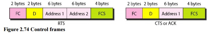
Data Frames: Data frames are used for carrying
data and control information.
Related Topics