Chapter: Computer Networks : Data Link Layer
High-level Data Link Control (HDLC)
HDLC:
High-level
Data Link Control (HDLC) is a bit-oriented protocol for communication over
point-to-point and multipoint links. Configurations and transfer modes HDLC
provides two common transfer modes that can be used in different
configurations: normal response mode (NRM) and asynchronous balanced mode
(ABM).
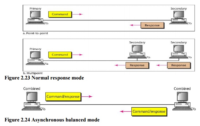
a. Normal Response Mode
In normal
response mode (NRM), the station configuration is unbalanced. We have one primary
station and multiple secondary stations. A primary station can send commands; a
secondary station can only respond. The NRM is used for both point-to-point and
multiple-point links.
b. Asynchronous Balanced Mode
In
asynchronous balanced mode (ABM), the configuration is balanced. The link is
point-to-point, and each station can function as a primary and a secondary
(acting as peers). This is the common mode today.
1. Frames:
HDLC
defines three types of frames: information frames (I-frames), supervisory
frames (S-frames), and unnumbered frames (U-frames). I-frames are used to
transport user data and control information relating to user data
(piggybacking). S-frames are used only to transport control information.
U-frames are reserved for system management. Information carried by U-frames is
intended for managing the link itself.
Frame
Format
Each
frame in HDLC may contain up to six fields, a beginning flag field, an address
field, a control field, an information field, a frame check sequence (FCS)
field, and an ending flag field. In multiple-frame transmissions, the ending
flag of one frame can serve as the beginning flag of the next frame.
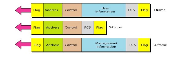
Figure 2.25 HDLC Frames
Fields
Let us
now discuss the fields and their use in different frame types.
Flag field. The flag field of an HDLC frame
is an 8-bit sequence with the bit pattern01111110 that identifies both the
beginning and the end of a frame and serves as a synchronization pattern for
the receiver.
Address field. The second field of an HDLC
frame contains the address of the secondarystation. If a primary station
created the frame, it contains a to
address. If a secondary creates the frame, it contains a from address. An address field can be 1 byte or several bytes
long, depending on the needs of the network. One byte can identify up to 128
stations.
Control field. The control field is a 1- or
2-byte segment of the frame used for flow anderror control. The interpretation
of bits in this field depends on the frame type. We discuss this field later
and describe its format for each frame type.
Information field. The information field contains
the user's data from the network layer ormanagement information. Its length can
vary from one network to another.
FCS field. The frame check sequence (FCS)
is the HDLC error detection field. It cancontain either a 2- or 4-byte ITU-T
CRC.
2. Control Field
The
control field determines the type of frame and defines its functionality. The
format is specific for the type of frame.
a. Control Field for I-Frames
I-frames
are designed to carry user data from the network layer. The subfields in the
control field are used to define these functions. The first bit defines the
type. If the first bit of the control field is 0, this means the frame is an
I-frame. The next 3 bits, called N(S), define the sequence number of the frame.
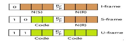
Figure 2.26 Control field format for the different frame
types
b. Control Field for S-Frames
Supervisory
frames are used for flow and error control whenever piggybacking is either
impossible or inappropriate. S-frames do not have information fields. If the
first 2 bits of the control field is 10, this means the frame is an S-frame.
The last 3 bits, called N(R), corresponds to the acknowledgment number (ACK) or
negative acknowledgment number (NAK) depending on the type of S-frame. The 2
bits called code is used to define the type of S-frame itself.
c. Control Field for V-Frames
Unnumbered
frames are used to exchange session management and control information between
connected devices. Unlike S-frames, U-frames contain an information field, but
one used for system management information, not user data. U-frame codes are
divided into two sections: a 2-bit prefix before the P/F bit and a 3-bit suffix
after the P/F bit. Together, these two segments (5 bits) can be used to create
up to 32 different types of U-frames.
Example 2.6:
Connection/Disconnection
Node A
asks for a connection with a set asynchronous balanced mode (SABM) frame; node
B gives a positive response with an unnumbered acknowledgment (VA) frame. After
these two exchanges, data can be transferred between the two nodes (not shown
in the figure). After data transfer, node A sends a DISC (disconnect) frame to
release the connection; it is confirmed by node B responding with a VA
(unnumbered acknowledgment).
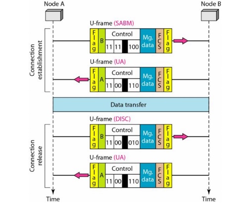
Figure 2.27 Example for connection and
disconnection
Example 2.7: Piggybacking without Error
Node A
begins the exchange of information with an I-frame numbered 0 followed by
another I-frame numbered 1. Node B piggybacks its acknowledgment of both frames
onto an I-frame of its own. Node B's first I-frame is also numbered 0 [N(S)
field] and contains a 2 in its N(R) field, acknowledging the receipt of Ns
frames 1 and 0 and indicating that it expects frame 2 to arrive next. Node B
transmits its second and third I-frames (numbered 1 and 2) before accepting
further frames from node A. Its N(R) information, therefore, has not changed: B
frames 1 and 2 indicate that node B is still expecting Ns frame 2 to arrive
next. Node A has sent all its data.
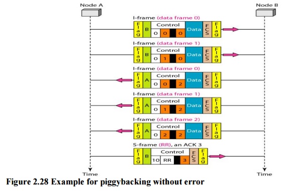
Therefore,
it cannot piggyback an acknowledgment onto an I-frame and sends an S-frame
instead. The RR code indicates that A is still ready to receive. The number 3
in the N(R) field tells B that frames 0, 1 & 2 have all been accepted and
that A is now expecting frame number 3.
Related Topics