Chapter: Computer Networks : Data Link Layer
Data link control- Framing
Framing
Data
transmission in the physical layer means moving bits in the form of a signal
from the source to the destination. The physical layer provides bit
synchronization to ensure that the sender and receiver use the same bit
durations and timing.
1. Fixed size Framing:
Frames
can be of fixed or variable size. In fixed-size framing, there is no need for
defining the boundaries of the frames; the size itself can be used as a
delimiter.
2. Variable-Size Framing
In
variable-size framing, we need a way to define the end of the frame and the
beginning of the next. Historically, two approaches were used for this purpose:
a character-oriented approach and a bit-oriented approach.
a. Character-Oriented Protocols
In a
character-oriented protocol, data to be carried are 8-bit characters from a
coding system such as ASCII. The header, which normally carries the source and
destination addresses and other control information, and the trailer, which
carries error detection or error correction redundant bits, are also multiples
of 8 bits. To separate one frame from the next, an 8-bit (I-byte) flag is added
at the beginning and the end of a frame.

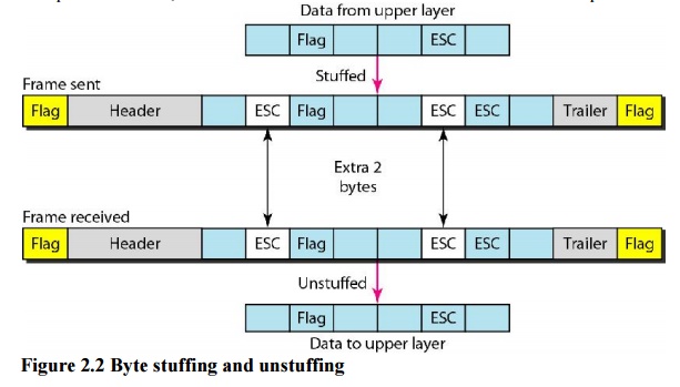
Byte
stuffing by the escape character allows the presence of the flag in the data
section of the frame, but it creates another problem. The receiver removes the
escape character, but keeps the flag, which is incorrectly interpreted as the
end of the frame. The escape characters that are part of the text must also be
marked by another escape character. In other words, if the escape character is
part of the text, an extra one is added to show that the second one is part of
the text.

b. Bit-Oriented Protocols
In a
bit-oriented protocol, the data section of a frame is a sequence of bits to be
interpreted by the upper layer as text, graphic, audio, video, and so on.
However, in addition to headers (and possible trailers), we still need a
delimiter to separate one frame from the other. Most protocols use a special
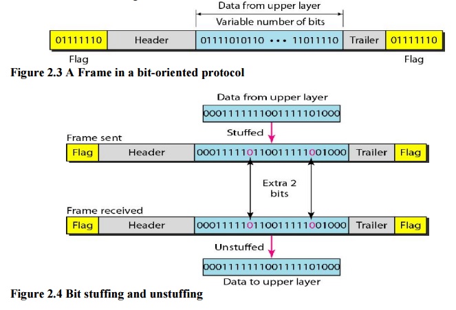
8-bit pattern flag 01111110 as the delimiter to define the beginning and the
end of the frame, as shown in Figure 2.3.

Figure 2.4 shows bit stuffing at the sender and bit removal at the
receiver. Note that even if we have a 0 after five 1s, we still stuff a 0. The
0 will be removed by the receiver.
This
means that if the flag like pattern 01111110 appears in the data, it will
change to 011111010 (stuffed) and is not mistaken as a flag by the receiver.
The real flag 01111110 is not stuffed by the sender and is recognized by the
receiver.
Related Topics