Chapter: Special Electrical Machines : Stepping Motor
Single Stack Variable Reluctance Stepper Motor: Construction and Principle of Operation
SINGLE STACK VARIABLE RELUCTANCE
STEPPER MOTOR
1. Construction:
The VR
stepper motor characterized by the fact there is no permanent magnet either on
the rotor or the stator. The construction of a 3-phase VR stepper motor with 6
poles on the stator and 4-pole on the rotor as shown.
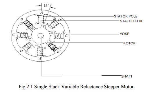
The
Stator is made up of silicon steel stampings with inward projected even or odd
number of poles or teeth. Each and every stator poles carries a field coil an
exciting coil. In case of even number of poles the exciting coils of opposite
poles are connected in series. The two coils are connected such that their MMF
gets added .the combination of two coils is known as phase winding.
The rotor
is also made up of silicon steel stampings with outward projected poles and it
does not have any electrical windings. The number of rotor poles should be
different from that of stators in order to have self-starting capability and bi
direction. The width of rotor teeth should be same as stator teeth. Solid
silicon steel rotors are extensively employed. Both the stator and rotor
materials must have lowering a high magnetic flux to pass through them even if
a low magneto motive force is applied.
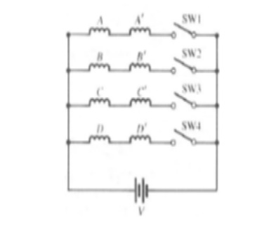
2. Electrical Connection
Electrical
connection of VR stepper as shown fig. Coil A and A‘ are connected in series to
form a phase winding. This phase winding is connected to a DC source with the
help of semiconductor switch S1.Similary B and B‘ and C and C‘ are connected to
the same source through semiconductor switches S2 and S3 respectively. The
motor has 3 –phases a, b and c.
v a phase
consist of A and A‘ Coils
v b phase
consist of B and B‘ Coils
v c phase
consist of C and C‘ Coils
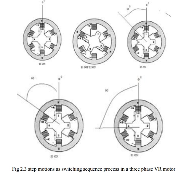
3. Principle of Operation
It works
on the principle of variable reluctance. The principle of operation of VR
stepper motor explained by referring fig.
(a).Mode 1 : One phase ON or full step operation
In this
mode of operation of stepper motor only one phase is energized at any time. If
current is applied to the coils of phase ‗a‘ (or) phase ‗a‘ is excited, the
reluctance torque causes the rotor to run until aligns with the axis of phase
a. The axis of rotor poles 1 and 3 are in alignment with the axis of stator
poles ‗A‘ and ‗A‘‘. Then angle θ = 0° the magnetic reluctance is minimized and
this state provides a rest or equilibrium position to the rotor and rotor
cannot move until phase ‗a‘ is energized.
Next
phase b is energized by turning on the semiconductor switch S2 and phase ‗a‘ is
de –energized by turning off S1.Then the rotor poles 1 and 3 and 2 and 4
experience torques in opposite direction. When the rotor and stator teeth are
out of alignment in the excited phase the magnetic reluctance is large. The
torque experienced by 1 and 3 are in clockwise direction and that of 2 and 4 is
in counter clockwise direction. The latter is more than the former. As a result
the rotor makes an angular displacement of 30° in counterclockwise direction so
that B and B‘ and 2 and 4 in alignment. The phases are excited in sequence a, b
and c the rotor turns with a step of 30° in counter clockwise direction. The
direction of rotation can be reversed by reversing the switching sequence in
which are energized and is independent of the direction of currents through the
phase winding.
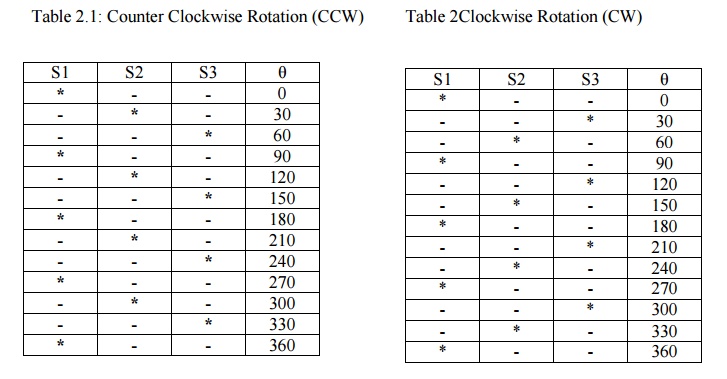
The truth table for mode I operation in counter and clockwise directions are given in the table
Table
2.1: Counter Clockwise Rotation (CCW) Table
2Clockwise Rotation (CW)
(b).Mode II: Two Phase on Mode
In this
mode two stator phases are excited simultaneously. When phases a and b are
energized together, the rotor experiences torque from both phases and comes to
rest in a point mid-way between the two adjacent full step position. If the
phases b and c are excited, the rotor occupies a position such that angle
between AA‘ axis of stator and 1-3 axis of rotor is equal to 45°.To reverse the
direction of rotation switching sequence is changed a and b,a and c etc. The
main advantage of this type of operation is that torque developed by the
stepper motor is more than that due to single phase ON mode of operation.
The truth
table for mode II operation in counter clockwise and clockwise directions is
given in a tableTable
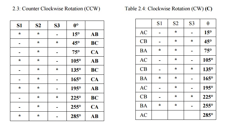
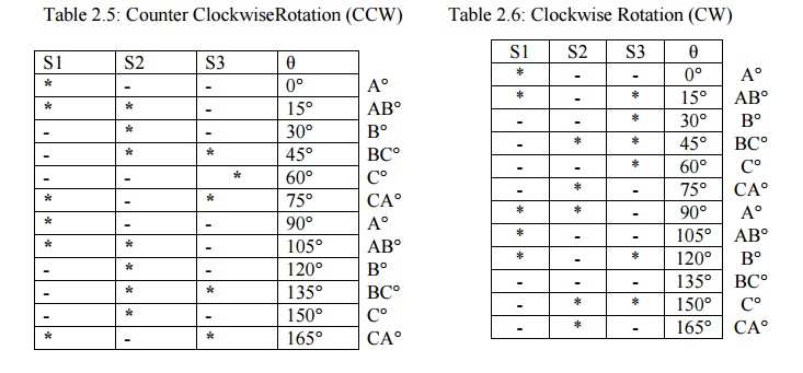
Mode III: Half step Mode
In this type
of mode of operation on phase is ON for some duration and two phases are ON
during some other duration. The step angle can be reduced from 30° to 15° by
exciting phase sequence a, a+b, b,b+c, c etc. The technique of shifting
excitation from one phase to another from a to b with an intermediate step of
a+b is known as half step and is used to realize smaller steps continuous half
stepping produces smoother shaft rotation.
The truth
table for mode III operation in counter and clockwise directions are given in
the table
Related Topics