Chapter: Digital Electronics : Synchronous and Asynchronous Sequential Circuits
Sequential Circuits Design Procedures
SEQUENTIAL CIRCUITS DESIGN PROCEDURES
We saw in the combinational circuits section how to design a combinational circuit from the given problem. We convert the problem into a truth table, then draw K-map for the truth table, and then finally draw the gate level circuit for the problem. Similarly we have a flow for the sequential circuit design. The steps are given below.
· Draw state diagram.
· Draw the state table (excitation table) for each output.
Looks like sequential circuit design flow is very much the same as for combinational circuit.
1. State Diagram
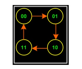
The state diagram is constructed using all the states of the sequential circuit in question. It builds up the relationship between various states and also shows how inputs affect the states.
To ease the following of the tutorial, let's consider designing the 2 bit up counter (Binary counter is one which counts a binary sequence) using the T flip-flop.
Below is the state diagram of the 2-bit binary counter.

2. State Table
The state table is the same as the excitation table of a flip-flop, i.e. what inputs need to be applied to get the required output. In other words this table gives the inputs required to produce the specific outputs.

3. K-map
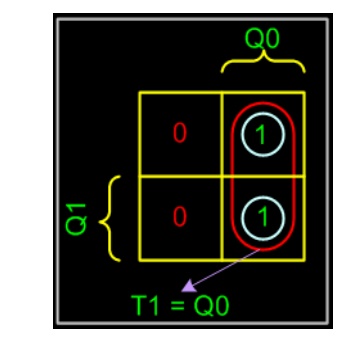
The K-map is the same as the combinational circuits K-map. Only difference: we draw K-map for the inputs i.e. T1 and T0 in the above table. From the table we deduct that we don't need to draw K-map for T0, as it is high for all the state combinations. But for T1 we need to draw the K-map as shown below, using SOP.

4. Circuit
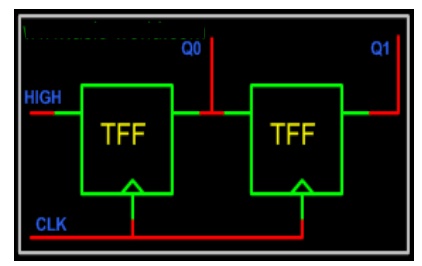
There is nothing special in drawing the circuit, it is the same as any circuit drawing from K-map output. Below is the circuit of 2-bit up counter using the T flip-flop.

Related Topics