Chapter: Operations Research: An Introduction : Network Models
Scope and Definition of Network Models
SCOPE AND DEFINITION OF NETWORK MODELS
A multitude of operations research situations can be modeled and solved
as networks (nodes connected by branches):
1. Design of an offshore natural-gas pipeline network connecting well heads
in the Gulf of Mexico to an inshore delivery point. The objective of the model
is to minimize the cost of constructing the pipeline.
2. Determination of the shortest route between two cities in an existing
network of roads.
3. Determination of the maximum capacity (in tons per year) of a coal
slurry pipeline network joining coal mines in Wyoming with power plants in
Houston. (Slurry pipelines transport coal by pumping water through specially
designed pipes.)
4. Determination of the time schedule (start and completion dates) for the
activ-ities of a construction project.
5. Determination of the minimum-cost flow schedule from oil fields to
refineries through a pipeline network.
The solution of these situations, and others like it, is accomplished
through a variety of network optimization algorithms. This chapter presents
four of these algorithms.
1. Minimal spanning tree (situation 1)
2. Shortest-route algorithm (situation 2)
3. Maximal-flow algorithm (situation 3)
4. Critical path (CPM) algorithm (situation 4)
For the fifth situation, the minimum-cost capacitated network algorithm
is presented in Section 20.1 on the CD.
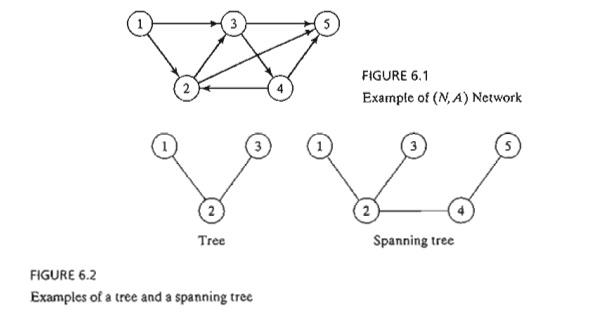
Network Definitions. A network consists of a set of nodes linked by arcs
(or branches). The notation for describing a network is (N, A), where N is the set of nodes and A is the set of arcs. As an illustration, the network in Figure 6.1 is
described as
N = {1,2,3,4,5}
A
= {(1,2), (1,3), (2,3), (2,5),
(3,4), (3,5), (4,2), (4,5)}
Associated with each network is a flow (e.g., oil products flow in a
pipeline and automobile traffic flows in highways). In general, the flow in a
network is limited by the capacity of its arcs, which may be finite or
infinite.
An arc is said to be directed or oriented if it allows positive flow in
one direction and zero flow in the opposite direction. A directed network has
all directed arcs.
A path is a sequence of distinct arcs that join two nodes through other
nodes regardless of the direction of flow in each arc. A path forms a cycle or
a loop if it con-nects a node to itself through other nodes. For example, in
Figure 6.1, the arcs (2,3), (3, 4), and (4,2) form a cycle.
A
connected network is such that every two distinct nodes are linked by at least
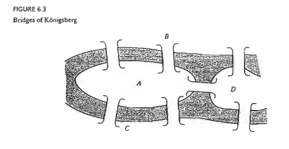
one path. The network in Figure 6.1 demonstrates this type of network. A tree
is a cycle-free connected network
comprised of a subset of all the nodes,
and a spanning tree is a tree that
links all the nodes of the network.
Figure 6.2 provides examples of a tree and a spanning tree from the network in
Figure 6.1.
Example
6.1-1 (Bridges
of Konigsberg)
The
Prussian city of Konigsberg (now Kalingrad in Russia) was founded in 1254 on
the banks of river Pergel with seven bridges connecting its four sections
(labeled A, B, C, and D) as shown in Figure 6.3. A
problem circulating among the inhabitants of the city was to find out if a round trip
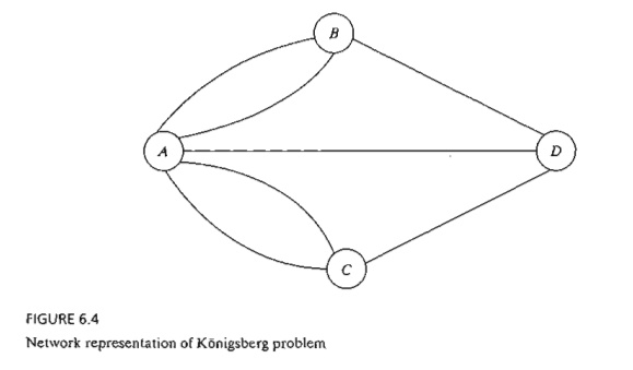
of the
four sections could be made with each bridge being crossed exactly once. No
limits were set on the number of times any of the four sections could be
visited.
In the
mid-eighteenth century, the famed mathematician Leonhard Euler developed a special
"path construction" argument to prove that it was impossible to make
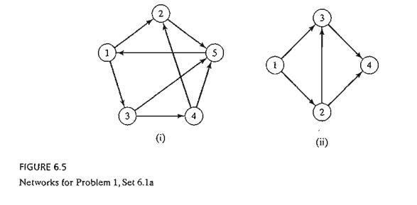
such a trip. Later, in the early nineteenth century the same problem was solved
by representing the situation as a net-work in which each of the four sections (A, B, C, and D) is a
node and each bridge is an arc join-ing applicable nodes, as shown in Figure
6.4.
The
network-based solution is that the desired round trip (starting and ending in
one sec-tion of the city) is impossible, because there are four nodes and each
is associated with an odd number of arcs, which does not
allow distinct entrance and exit (and hence distinct use of the bridges) to
each section of the city. The
example demonstrates how the solution of the problem is facilitated by using
network representation.
PROBLEM SET 6.1A
*1. For
each network in Figure 6.5 determine (a) a path, (b) a cycle, (c) a tree, and
(d) a span-ning tree.
2. Determine
the sets N and A for the networks in Figure 6.5.
3.Draw
the network defined by
N = {1,2,3,4,5,6}
A = {{1,2),(1,5),
(2,3), (2,4),(3,4), (3,5), (4,3),(4,6), (5,2),(5,6)}
*4.
Consider eight equal squares arranged in three rows, with two squares in the
first row, four in the second, and two in the third. The squares of each row
are arranged symmetrically about the vertical axis. It is desired to fill the
squares with distinct numbers in the range 1 through 8
so that
no two adjacent vertical, horizontal,
or diagonal squares hold consecutive numbers. Use some form of a network
representation to find the solution in a systematic way.
5. Three
inmates escorted by 3 guards must be transported by boat from the mainland to a
penitentiary island to serve their sentences. The boat cannot transfer more than
two per-sons in either direction. The inmates are certain to overpower the
guards if they outnumber them at any time. Develop a network model that designs
the boat trips in a manner that ensures a smooth transfer of the inmates.
Related Topics