Chapter: Mechanical and Electrical : Power Plant Engineering : Coal Based Thermal Power Plants
Process of the Rankine Cycle
Type of Basic Boilers thermodynamic
cycles process of the Rankine cycle
BOILER
CYCLES
In general, two important area of
application for thermodynamics are:
1. Power generation
2. Refregeration
Both are
accomplished by systems that operate in thermodynamic cycles such as:
a.
Power
cycles: Systems used to produce net power output and are often called engines.
Refrigeration
cycles: Systems used to produce refregeration effects are called refregerators
2. Vapour power cycles
In
this case, the working fluid exists in the vapour phase during one part of the
cycle and in the liquid phase during another part.
Vapour power cycles can be
categorized as
a.
Carnot
cycle
b.
Rankine
cycle
c.
Reheat
cycle
d.
Regenerative
cycle
e.
Binary
vapour cycle
Steam cycles (Ranking cycle)
The
Rankine cycle is a thermodynamic cycle. Like other thermodynamic cycle,
the maximum efficiency of the Ranking cycle is given by calculating the maximum
efficiency of the carnot cycle.
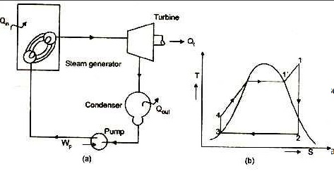
Process of the Rankine Cycle

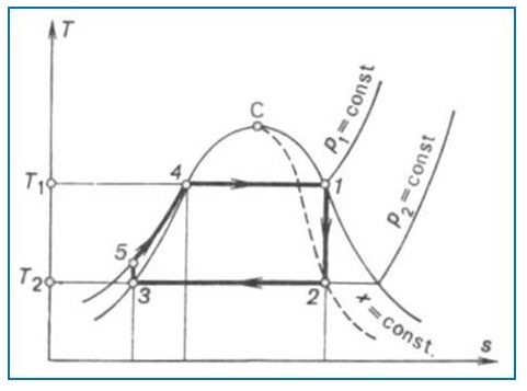
Figure:
Schematic rep
There are
four processes in the Rankine cycle, each changing the state of the working
fluid. These states are identified by number in the diagram above.
Process
3-4:
First, the working fluid (water) is enter the pump at
state 3 at saturated liquid and it is pumped (ideally isentropically) from low
pressure to high (operating) pressure of boiler by a pump to the state 4.
During this isentropic compression water temperature is slightly increased.
Pumping requires a power input (for example, mechanical or electrical). The
conservation of energy relation for pump is given as
Wpump = m (h4 - h3)
Process
4-1:
The high pressure compressed liquid enters a boiler at
state 4 where it is heated at constant pressure by an external heat source to
become a saturated vapour at statel’which in turn superheated to state 1
through super heater. Common heat source for power plant systems are coal (or
other chemical energy), natural gas, or nuclear power. The conservation of
energy relation for boiler is given as
Qin =m (h1 - h4)
Process
1 –2:
The superheated vapour enter the turbine at state 1 and
expands through a turbine to generate power output. Ideally, this expansion is
isentropic. This decreases the temperature and
pressure
of the vapour at state 2. The conservation of energy relation for turbine is
given as
Wturbine = m (h1 –h2)
Process
2 –3:
The vapour then enters a condenser at state 2. At this
state, steam is a saturated liquid-vapour mixture where it is cooled to become
a saturated liquid at state 3. This liquid then re-enters the pump and the
cycle is repeated. The conservation of energy relation for condenser is given
as
Qout = m (h2 –h3)
The exposed Rankine cycle can also prevent vapour
overheating, which reduces the amount of liquid condensed after the expansion
in the turbine.
Description
Rankine
cycles describe the operation of steam heat engines commonly found in power
generation plants. In such vapour power plants, power is generated by
alternatively vaporizing ng fluid (in many cases water, although refrigerants
such as ammonia in a Rankine cycle follows a closed loop and is re-used
constantly. Water vapour seen billowing from power plants is evaporating
cooling water, not working fluid. (NB: steam is invisible until it comes in
contact with cool, saturated air, at which point it condenses and forms the
white billowy clouds seen leaving cooling towers).
Variables
Qin- heat
input rate (energy per unit time) m= mass flow rate (mass per unit time)
W- Mechanical power used by or
provided to the system (energy per unit time)
h-
thermodynamic efficiency of the process (power used for turbine per heat input,
unit
less).
The thermodynamic efficiency of the
cycle as the ratio of net power output to heat input.
Wnet =(Wturbine -Wpump )or (Qin
-Qout )
h=Wnet / Qin
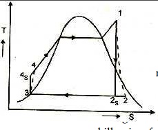
Real Rankine Cycle variation of Basic
Rankine Cycle
Real Ranking Cycle (Non-ideal)
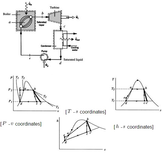
Figure:
In
a real Rankine cycle, the compression by the pump and the expansion in the
turbine are not isentropic. In other words, these processes are non-reversible
and entropy is increased during the two process (indicated in the figure). This
somewhat increases the power required by the pump and decreases the power
generated by the turbine. It also makes calculations more involved and
difficult.
Variation of the Basic Rankine Cycle:
Two main
variations of the basic Rankine cycle to improve the efficiency of the steam
cycles are done by incorporating Reheater and Regenerator in the ideal ranking
cycle.
Rankine
cycle with reheat
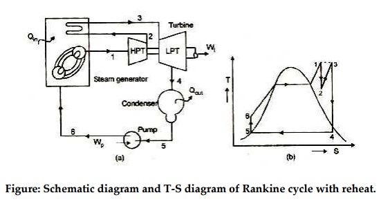
Figure: Schematic diagram and T-S
diagram of Rankine cycle with reheat.
In this variation, two turbines work in series. The first
accepts vapour from the boiler at high pressure. After the vapour has passed
through the first turbine, it re-enters the boiler and is reheated before
passing through a second, lower pressure turbine. Among other advantages, this
prevents the vapour from condensing during its expansion which can seriously
damage the turbine blades.
Related Topics