Chapter: Computer Networks : Physical Layer
OSI Model
OSI Model:
Established
in 1947, the International Standards Organization (ISO) is a multinational body
dedicated to worldwide agreement on international standards. An ISO standard
that covers all aspects of network communications is the Open Systems
Interconnection model. It was first introduced in the late 1970s.
An open
system is a set of protocols that allows any two different systems to
communicate regardless of their underlying architecture. The purpose of the OSI
model is to show how to facilitate communication between different systems
without requiring changes to the logic of the underlying hardware and software.
The OSI model is not a protocol; it is a model for understanding and designing
a network architecture that is flexible, robust, and interoperable.
ISO is the organization. OSI is the model.
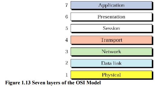
The OSI
model is a layered framework for the design of network systems that allows
communication between all types of computer systems. It consists of seven
separate but related layers, each of which defines a part of the process of
moving information across a network (see Figure 1.13).
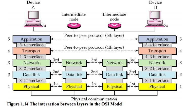
1. Layered architecture:
Figure
1.14 shows the layers involved when a message is sent from device A to device
B. As the message travels from A to B, it may pass through many intermediate
nodes. These intermediate nodes usually involve only the first three layers of
the OSI Model.
Each
layer defines a family of functions distinct from those of the other layers. By
defining and localizing functionality in this fashion, the designers created an
architecture that is both comprehensive and flexible.
2. Peer-to-Peer Processes:
At the
physical layer, communication is direct: In Figure 1.14, device A sends a
stream of bits to device B (through intermediate nodes). At the higher layers,
however, communication must move down through the layers on device A, over to
device B, and then back up through the layers. Each layer in the sending device
adds its own information to the message it receives from the layer just above
it and passes the whole package to the layer just below it.
At layer
1 the entire package is converted to a form that can be transmitted to the
receiving device. At the receiving machine, the message is unwrapped layer by
layer, with each process receiving and removing the data meant for it. For
example, layer 2 removes the data meant for it, and then passes the rest to
layer 3. Layer 3 then removes the data meant for it and passes the rest to
layer 4, and so on.
3. Interface between layers:
The
passing of the data and network information down through the layers of the sending
device and back up through the layers of the receiving device is made possible
by an interface between each pair of adjacent layers.
4. Organization of the layers:
The seven
layers can be thought of as belonging to three subgroups. Layers I, 2, and
3-physical, data link, and network-are the network support layers; they deal
with the physical aspects of moving data from one device to another. Layers 5,
6, and 7-session, presentation, and application-can be thought of as the user
support layers; they allow interoperability among unrelated software systems.
Layer 4, the transport layer ensures that what the lower layers have
transmitted is in a form that the upper layers can use. The upper OSI layers
are almost always implemented in software; lower layers are a combination of
hardware and software, except for the physical layer, which is mostly hardware.
In Figure
1.15, which gives an overall view of the OSI layers, D7 means the data unit at
layer 7, D6 means the data unit at layer 6, and so on. The process starts at
layer 7 (the application layer), then moves from layer to layer in descending,
sequential order. At each layer, a
header, or possibly a trailer,
can be added to the data unit. Commonly, the trailer is added only at layer 2.
When the formatted data unit passes through the physical layer (layer 1), it is
changed into an electromagnetic signal and transported along a physical link.

5. Encapsulation:
A packet
(header and data) at level 7 is encapsulated in a packet at level 6. The whole
packet at level 6 is encapsulated in a packet at level 5, and so on. In other
words, the data portion of a packet at level N - 1 carries the whole packet
(data and header and maybe trailer) from level N. The concept is called
encapsulation; level N - 1 is not aware of which part of the encapsulated
packet is data and which part is the header or trailer. For level N - 1, the
whole packet coming from level N is treated as one integral unit.
Related Topics