Chapter: Computer Networks : Physical Layer
Circuit-Switched Networks
CIRCUIT-SWITCHED NETWORKS:
A
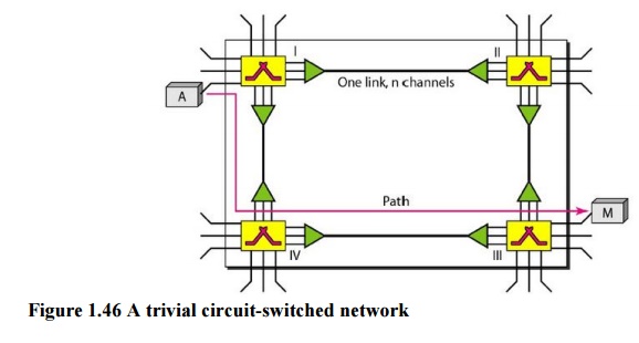
circuit-switched network consists of a set of switches connected by physical
links. A connection between two stations is a dedicated path made of one or
more links. However, each connection uses only one dedicated channel on each
link. Each link is normally divided into n
channels by using FDM or TDM.
A circuit-switched network is made of a set of
switches connected by physical links, in which each link is divided into n channels.

The end
systems, such as computers or telephones, are directly connected to a switch.
We have shown only two end systems for simplicity. When end system A needs to
communicate with end system M, system A needs to request a connection to M that
must be accepted by all switches as well as by M itself. This is called the
setup phase; a circuit (channel) is reserved on each link, and the combination
of circuits or channels defines the dedicated path. After the dedicated path
made of connected circuits (channels) is established, data transfer can take
place. After all data have been transferred, the circuits are tom down.
We need
to emphasize several points here:
·
Circuit switching takes place at the physical
layer.
·
Before starting communication, the stations must
make a reservation for the resources to be used during the communication. These
resources, such as channels (bandwidth in FDM and time slots in TDM), switch
buffers, switch processing time, and switch input/output ports, must remain
dedicated during the entire duration of data transfer until the teardown phase.
·
Data transferred between the two stations are not
packetized (physical layer transfer of the signal). The data are a continuous
flow sent by the source station and received by the destination station,
although there may be periods of silence.
·
There is no addressing involved during data
transfer. The switches route the data based on their occupied band (FDM) or
time slot (TDM). Of course, there is end-to-end addressing used during the
setup phase.
In circuit switching, the resources need to be
reserved during the setup phase; the resources remain dedicated for the entire
duration of data transfer until the teardown phase.
Example 1.1
As a
trivial example, let us use a circuit-switched network to connect eight
telephones in a small area. Communication is through 4-kHz voice channels. We
assume that each link uses FDM to connect a maximum of two voice channels. The
bandwidth of each link is then 8 kHz. Telephone 1 is connected to telephone 7;
2 to 5; 3 to 8; and 4 to 6. Of course the situation may change when new
connections are made. The switch controls the connections

Circuit-Switched Technology in Telephone Networks:
The
telephone companies have previously chosen the circuit switched approach to
switching in the physical layer; today the tendency is moving toward other
switching techniques. For example, the telephone number is used as the global
address, and a signaling system (called SS7) is used for the setup and teardown
phases.
Switching at the physical layer in the traditional
telephone network uses the circuit-switching approach.
Related Topics