Chapter: Mechanical : Computer Aided Design : Fundamentals of Computer Graphics
Fundamentals of Computer Graphics
FUNDAMENTALS OF COMPUTER GRAPHICS
Introduction of CAD
In the mid of 1970s, as computer aided
design starts to offer more potential than just a skill to replicate manual
drafting with electronic drafting, the cost gain for companies to switch to CAD
became obvious. The benefit of CAD methods over manual drafting are the
capabilities one often takes for established from computer systems; automated
creation of Bill of Material, interference checking, auto layout in integrated circuits.
Product
cycle
Product cycle integrate processes,
people, data, and business and gives a product information for industries and
their extended activity. Product cycle is the process of managing the entire
lifecycle of a product from starting, through design and manufacture, to repair
and removal of manufactured products.
Product cycle methods assist association
in managing with the rising difficulty and engineering challenges of developing
new products for the worldwide competitive markets.
Product lifecycle management (PLM) can
be part of one of the following four fundamentals of a manufacturing
information technology structure.
(i)
Customer Relationship Management (CRM)
(ii)
Supply Chain Management (SCM)
(iii)
Enterprise resource planning (ERP)
(iv)
Product Planning and Development (PPD).
The
core of PLM is in the formation and management of all product information and
the technology used to access this data and knowledge. PLM as a discipline
appeared from tools such as CAD, CAM and PDM, but can be viewed as the
combination of these tools with processes, methods and people through all
stages of a product’slife cycle. PLM is not just about software technology but
is
also
a business approach.
Product Cycle Model
There are several Product cycle models in industry
to be considered, one of the possible product
cycle
is given below (Fig.1.1.):
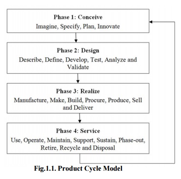
Fig.1.1.
Product Cycle Model
Step
1: Conceive
Imagine,
Specify, Plan, Innovate
The first step is the definition of the
product requirements based on company, market and customer. From this
requirement, the product's technical data can be defined. In parallel, the
early concept design work is performed defining the product with its main
functional features. Various media are utilized for these processes, from paper
and pencil to clay mock-up to 3D Computer Aided Industrial Design.
Step
2: Design
Describe,
Define, Develop, Test, Analyze and Validate
This is where the completed design and development
of the product begins, succeeding to prototype testing, through pilot release
to final product. It can also involve redesign and ramp for improvement to
existing products as well as planned obsolescence. The main tool used for
design and development is CAD. This can be simple 2D drawing / drafting or 3D
parametric feature based solid/surface modeling.
This step covers many engineering
disciplines including: electronic, electrical, mechanical, and civil. Besides
the actual making of geometry there is the analysis of the components and
assemblies.
Optimization, Validation and Simulation
activities are carried out using Computer Aided Engineering (CAE) software.
These are used to perform various tasks such as: Computational Fluid Dynamics
(CFD); Finite Element Analysis (FEA); and Mechanical Event Simulation (MES).
Computer Aided Quality (CAQ) is used for activities such as Dimensional tolerance
analysis. One more task carried out at this step is the sourcing of bought out
components with the aid of procurement process.
Step 3: Realize
Manufacture, Make, Build, Procure, Produce, Sell and
Deliver
Once the design of the
components is complete the method of manufacturing is finalized. This includes
CAD operations such as generation of CNC Machining instructions for the
product’s component as well as tools to manufacture those components, using
integrated Computer Aided Manufacturing (CAM) software.
It includes Production Planning tools
for carrying out plant and factory layout and production simulation. Once
details components are manufactured their geometrical form and dimensions can
be verified against the original data with the use of Computer Aided Inspection
Equipment (CAIE). Parallel to the engineering tasks, sales and marketing work
take place. This could consist of transferring engineering data to a web based
sales configuration.
Step
4: Service
Use,
Operate, Maintain, Support, Sustain, Phase-out, Retire, Recycle and Disposal.
The
final step of the lifecycle includes managing of information related to service
for repair and maintenance, as well as recycling and waste management
information. This involves using tools like Maintenance, Repair and Operations
Management software.
Design Process
The design process includes series of
steps that engineers apply in making functional products and processes. The
parts of the process often need to be repeated many times before production of
a product can start. The parts that get iterated and the number of such design
cycles in any given project can be highly changeable.
One
method of the engineering design process focuses on the following common
aspects:
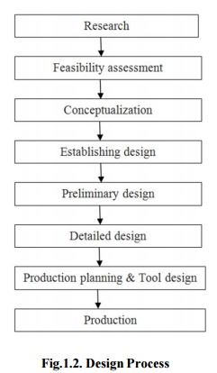
Fig.1.2.
Design Process
1.
Research
A
considerable amount of time is used on research, or finding information.
Consideration should be given to the available applicable literature, issues
and successes linked with avaialbe solutions, and need of marketplaces.
The
basis of information should be significant, including existing results. Reverse
engineering can be a successful technique if other solutions are available in
the market. Added sources of information include the trade journals, available
government documents, local libraries, vendor catalogs and personal
organizations.
2.
Feasibility assessment
The feasibility study
is an analysis and assessment of the possible of a proposed design which is
based on detail investigation and research to maintain the process of decision
creation. The feasibility assessment helps to focus the scope of the project to
spot the best situation. The purpose of a feasibility assessment is to verify
whether the project can continue into the design phase.
3. Conceptualization
A Concept Study is the stage of project
planning that includes developing ideas and taking into account the all
features of executing those ideas. This stage of a project is done to reduce
the likelihood of assess risks, error and evaluate the potential success of the
planned project.
4.
Establishing the design requirements
Establishing design requirements is one
of the most essential elements in the design practice, and this task is usually
performed at the same time as the feasibility analysis. The design requirements
control the design of the project all over the engineering design process. A
few design
requirements comprise maintainability, hardware and
software parameters, availability, and testability.
5.
Preliminary design
The preliminary design
fills the gap between the design concept and the detailed design phase. During
this task, the system configuration is defined, and schematics, diagrams, and
layouts of the
project will offer
early project configuration. In detailed design and optimization, the
parameters of the part being produced will change, but the preliminary design
focuses on creating the common framework to construct the project.
6. Detailed
design
The next phase of
preliminary design is the Detailed Design which may includes of procurement
also. This phase builds on the already developed preliminary design, aiming to
further
develop each phase of
the project by total description through drawings, modeling as well as specifications.
The advancement CAD
programs have made the detailed design phase more competent. This is because a
CAD program can offer optimization, where it can shrink volume without
compromising the part's quality. It can also calculate displacement and stress
using the FEM to find stresses throughout the part. It is the responsibility of
designer to find whether these stresses and displacements are acceptable, so
the part is safe.
7. Production
planning and tool design
The production planning and tool design is more than
planning how to mass-produce the project and which tools should be used in the
manufacturing of the component. Tasks to complete in this stage include
material selection, identification of the production processes, finalization of
the sequence of operations, and selection of jigs, fixtures, and tooling. This
stage also includes testing a working prototype to confirm the created part
meets qualification standards.
With the finishing of
qualification testing and prototype testing, the design process is completed.
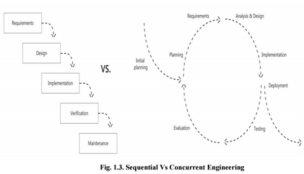
Sequential
and Concurrent Engineering
Table
1.1. Sequential Vs Concurrent Engineering
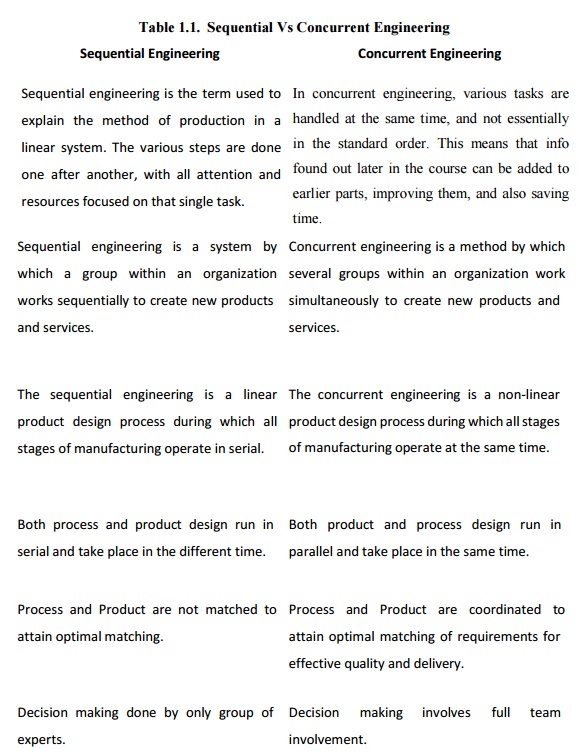
Sequential Engineering
Sequential
engineering is the term used to explain the method of production in a linear
system. The various steps are done one after another, with all attention and
resources focused on that single task.
Sequential engineering
is a system
by which a
group within an
organization works sequentially
to create new products and services.
The
concurrent engineering is a non-linear product design process during which all
stages of manufacturing operate at the same time.
Both
process and product design run in serial and take place in the different time.
Process
and Product are not matched to attain optimal matching.
Decision
making done by only group of
experts.
Concurrent Engineering
In
concurrent engineering, various tasks are handled at the same time, and not
essentially in the standard order. This means that info found out later in the
course can be added to earlier parts, improving them, and also saving time.
Concurrent
engineering is a method by which several groups within an organization work
simultaneously to create new products and
services.
The sequential
engineering is a
linear product design process
during which all stages of manufacturing
operate in serial.
Both
product and process design run in parallel and take place in the same time.
Process and
Product are coordinated
to attain optimal matching of requirements for effective quality and
delivery.
Decision making
involves full team involvement.
Computer Aided Design
CAD is the intersection
of Computer Graphics, Geometric modeling and Design tools (Fig.1.4.). The concepts
of computer graphics and geometric modeling and must be used innovatively to
serve the design process.
CAD
is the function of computer systems to support in the creation, modification,
analysis, or optimization of a design.
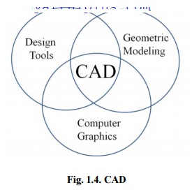
Fig.
1.4. CAD
CAD software for design
uses either vector-based graphics to explain the objects of traditional
drafting, or may also develop raster graphics showing the overall look of
designed objects. During the manual drafting of engineering drawings, the output
of CAD must convey information, like dimensions, materials, processes, and
tolerances.
CAD is a significant
industrial art used in many purposes, including industrial and architectural
design, shipbuilding, automotive, and aerospace industries, and many more. CAD
is also extensively used to create computer animation for special effects in
movies, and technical manuals, frequently called as Digital Content Creation.
CAD software packages provide the
designer with a multi window environment with animation which is regularly used
in Digital Content Creation. The animations using wire frame modeling helps the
designer to see into the interior of object and to observe the behaviors of the
inner components of the assembly during the motion.
CAD Technology
Initially software
for CAD systems
was developed with
computer languages such
as
FORTRAN
but with the development of object-oriented programming
methods this has completely changed. Classic modern parametric attribute based
modeler and freeform surface
systems are developing around a number of key ‘C’modules.
A CAD system can be
seen as develop from the interaction of a Graphical User
Interface (GUI) with NURBS geometry and
Boundary representation data through a kernel for geometric
modeling. A geometry constraint engine may also be
employed to organize the associative relationships between
components in an assembly.
Unexpected facilities
of these relationships have led to a new form of prototyping
called digital
prototyping. In
difference to physical prototypes, which involve manufacturing time in the
design. CAD models can be created by a computer after the physical prototype
has been scanned using an CT
scanning
device. Based on the nature of the business, digital or physical prototypes can
be primarily
selected according to specific requirements.
Currently, no special
hardware is required for CAD software. However, some special CAD systems can do
graphically and computationally intensive tasks, so a higher end graphics card,
high speed CPUs may be suggested. CAD systems exist for all the major platforms
and some packages even
perform multiple platforms.
The human-machine
interface is generally
through a mouse but can
also be using
a
digitizing graphics
tablet. Handling of the view of the part on the screen is also sometimes done
with the help of a Space mouse or Space Ball. Special CAD systems also support
stereoscopic glasses for viewing the 3D
objects.
CAD Tools
The
CAD tools are mainly using for graphics applications and modeling. Aids such a
color, grids, geometric modifiers and group facilitate structural geometric
models. Visualization is achieved through shaded components and animation which
focus design conceptualization, communication and interference detection. FEM
packages provide optimization in shape and structure. Adding tolerances,
tolerance analysis and investigating the effect of manufacturing on the design
can perform by utilizing CAD tools (Table 1.2).
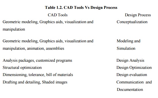
Table 1.2. CAD Tools Vs Design
Process
CAD Tools : Design Process
Geometric
modeling, Graphics aids, visualization and manipulation : Conceptualization
Geometric
modeling, Graphics aids, visualization and Modeling
and manipulation, animation, assemblies : Simulation
Analysis
packages, customized programs : Design
Analysis
Structural
optimization : Design Optimization
Dimensioning,
tolerance, bill of materials : Design
evaluation
Drafting
and detailing, Shaded images :
Communication and Documentation
Uses of CAD
CAD is one of the tools used by
designers and engineers and is used in different ways depending on the
profession of the customer and the type of software.
CAD is one of the Digital Product
Development activities within the Product
Lifecycle Management
practices with other tools, which are either integrated modules or individual,
such as:
· Computer Aided
engineering (CAE) and Finite Element
Analysis (FEA)
· Computer Aided
Manufacturing (CAM)
· Realistic
Rendering and Simulation.
· Product
Data Management (PDM).
CAD is also used for
the development of photo simulations that are frequently necessary in the
preparation of Environmental Impact Reports, in which proposed CAD buildings
are superimposed into photographs of existing situation to represent what that
conditions will be like, where the proposed services are allowed to be built.
Parameters and constraints can be used
to get the size, shape, and other properties of the modeling elements. The
features of the CAD system can be used for the several tools for measurement
such as yield strength, tensile strength and electrical or electro-magnetic
properties.
CAD System Architecture
Computer architecture
is a pattern describing how a group of software and hardware technology
standards relate to form a computer system. In general, computer architecture
refers to how a computer is designed and what technologies it is compatible
with. Computer architecture is likened to the art of shaping the needs of the
technology, and developing a logical design and standards based on needs.
In CAD, Computer
architecture is a set of disciplines that explains the functionality, the
organization and the introduction of computer systems; that is, it describes
the capabilities of a computer and its programming method in a summary way, and
how the internal organization of the system is designed and executed to meet
the specified facilities. Computer architecture engages different aspects,
including instruction set architecture design, logic design, and
implementation. The implementation includes Integrated Circuit Design, Power,
and Cooling. Optimization of the design needs expertise with Compilers, Operating
Systems and Packaging.
Instruction
set architecture
An instruction set architecture is the interface between the software and hardware and also can be observed as the programmer's view of the machine. Computers do not understand high level languages, if any, language elements that translate directly into a machine's native op codes.
Related Topics