Chapter: Mechanical : Computer Aided Design : Fundamentals of Computer Graphics
Fundamentals of Computer Graphics
FUNDAMENTALS OF COMPUTER GRAPHICS
PRODUCT LIFE CYCLE (PLC)
Every product goe s through a cycle from birth,
followed by an initial growth stage, a relatively stable matured period, and
finally into a declining stage that eventually ends in the death of the product
as shown schematically in Figure.
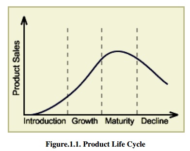
Figure.1.1.
Product Life Cycle
3.5. Introduction
stage: In this stage the product is new and the customer acc
eptance is low and hence the sales are low.
3.6. Growth
stage: Knowledge of the product and its capabilities reaches to a g
rowing number of customers.
3.7. Maturity
stage: The produ ct is widely acceptable and sales are now stable ,
and it grows with the same rate as the econ omy as a whole grows.
3.8.
Decline stage: At some
p oint of time the product enters the decline st age. Its sales start decreasing
because of a n ew and a better product has entered the market to fulfill the
same customer requirements.
PRODUCT LIFE CYCLE (PLC) FOR
CONTINUOUS IMPROVEMENT
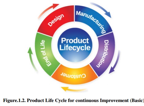
Figure.1.2.
Prod uct Life Cycle for continuous Improvement ( Basic)
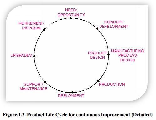
Figure.1.3.
Produc t Life Cycle for continuous Improvement (D etailed)
TECHNOLOGY DEVELOPMENT CYCLE
The development of a new technology
follows a typical S-shaped curve. In its early stage, the progress is limited
by the lack of ideas. A single good idea can make several other god ideas
possible, and the rate of progress is exponential. Gradually the growth becomes
linear when the fundamental ideas are in place and the progress is concerned
with filling the gaps between, the key ideas.
It is during this time when the commercial
exploitation flourishes. But with time the technology begins to run dry and
increased improvements come with greater difficulty. This matured technology
grows slowly and approaches a limit asymptotically.
The success of a technology based company lies in its capabilities of
recognizing when the core technology on which the company’s products are based
begin to mature and through an active R&D program, transfer to another
technology growth curve which offers greater possibilities.
![]()
![]()
![]()
![]()
![]()
![]()
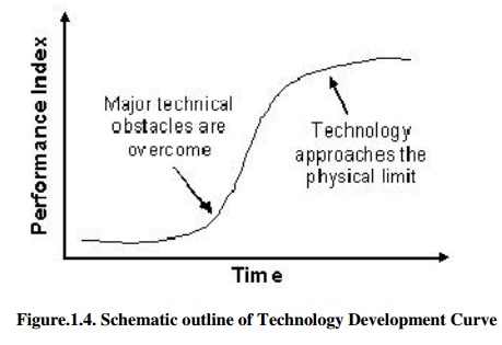
Figure.1.4. Schematic outline of Technology
Development Curve
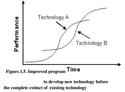
Figure.1.5. Improved program to develop new
technology before the complete extinct of existing technology
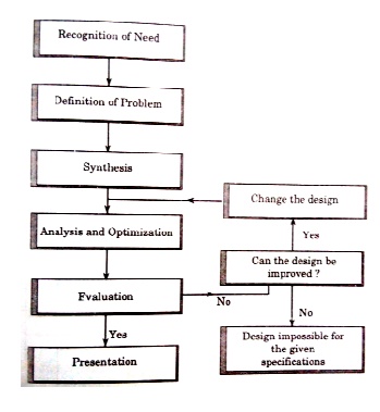
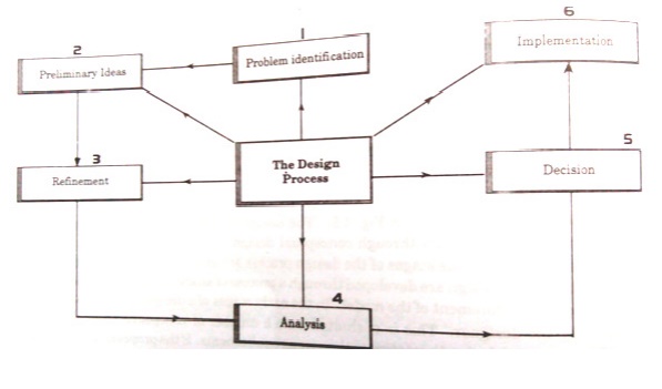
THE DESIGN PROCESS -
INTRODUCTION
The Engineering Design Process is the formulation of
a plan to help an engineer build a product with a specified performance goal.
This process involves a number of steps, and parts of the process may need to
be repeated many times before production of a final product can begin.
It is a decision making process (often iterative) in
which the basic sciences, mathematics, and engineering sciences are applied to
convert resources optimally to meet a stated objective. Among the fundamental
elements of the design process are the establishment of objectives and
criteria, synthesis, analysis, construction, testing and evaluation.
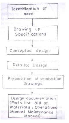
The Engineering Design process is a multi-step
process including the research, conceptualization, feasibility assessment,
establishing design requirements, preliminary design, detailed design,
production planning and tool design, and finally production.
1. Steps
involved in Enginee ring Design process
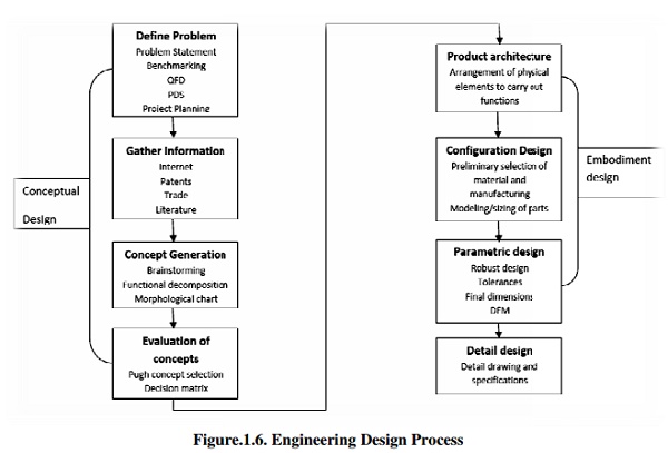
Figure.1.6.
Engineering Design Process
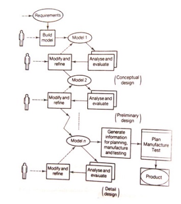
Conceptual Design
It is a process in which we in
itiate the design and come up with a number of design concepts and then narrow
down to the singl e best concept. This involved the following step s.
•
Identification of customer needs: The
mail objective of this is to completely understand the customers’ needs
and to c ommunicate them to the design team
•
Problem definition: The
mail goal of this activity is to create a statement that describes what all
needs to be accomplished to meet the needs of the customers’ requirem ents.
•
Gathering Information: In this
step, we collect all the information that can be helpful for developing
and translating the customers’ needs into engineering design.
•
Conceptualization: In thi
s step, broad sets of concepts are generated th at can potentially satisfy
the problem statem ent
(5) Concept selection: The main objective
of this step is to evaluate the various design concepts, modifying and evolving
into a single preferred concept.
Embodiment Design
It is a process where the
structured development of the design concepts takes place. It is in this phase
that decisions are made on strength, material selection, size shape and spatial
compatibility. Embodiment design is concerned with three major tasks – product
architecture, configuration design, and parametric design.
a.
Product architecture: It is
concerned with dividing the overall design system into small subsystems
and modules. It is in this step we decide how the physical components of the
design are to be arranged in order to combine them to carry out the functional
duties of the design.
b. Configuration
design: In this process we determine what all features are required
in the various parts / components and how these features are to be
arranged in space relative to each other.
c. Parametric
design: It starts with information from the configuration design
process and aims to establish the exact dimensions and tolerances of the
product. Also, final decisions on the material and manufacturing processes are
done if it has not been fixed in the previous process. One of the important
aspects of parametric designs is to examine if the design is robust or not.
Detail Design
It is in this phase the design is
brought to a state where it has the complete engineering description of a
tested and a producible product. Any missing information about the arrangement,
form, material, manufacturing process, dimensions, tolerances etc of each part
is added and detailed engineering drawing suitable for manufacturing are
prepared.
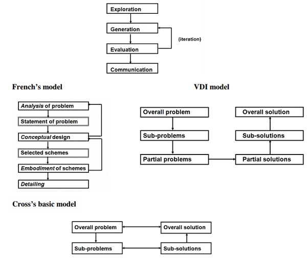
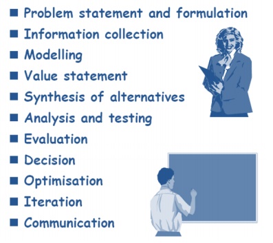
2. Models of the Design Process
Designers
have to:
Explore -
the problem ‘territory’
Generate
- solution concepts
Evaluate
- alternative solution concepts
Communicate
- a final proposal
A simple
model of the design process, derived from what designers have to do
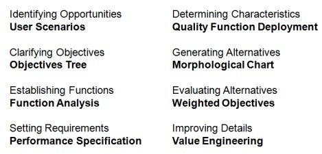
3. New
Design Procedures
4. Need for Applying Technoology in the Design
Process
Design
is the essence o f engineering
Starts
with recognition of some need
Progresses
to physical implementation
Results
may be simple or complex
Design
can be of two k ind:
O Something com pletely new , or
An improved f orm of something already
in existence
MORPHOLOGY OF DESIGN
The
consideration of the product life from its conception to retire ment.....
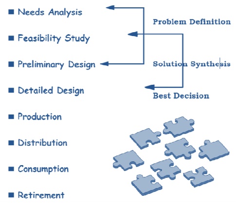
Anatomy of Design
Detailed
examination of th e engineer’s actions as he/she identifies and solves the
problem:
1.Needs Analysis
Creation
begins by recognizing a need
O
Apparent fr om observation
O
Results of a detailed study
O
A specific s et of circumstances
Results
in a primiti ve statement
O
Fact or opi nion
O
Does the ne ed exist and is it realistic?
O
Does it exis t now or will it exist in the future?
O
Is it a new need? (new material or physical principle)
Often
depends on c ircumstances
Needs
analysis once through the Anatomy provides a good star ting point for the
Feasibility Study
2.
Feasibility Study
Designs can be futile unless satisfying the original
need is feasible
At this stage, the product appears in abstract
forms, but is they feasible???
Alternative solutions must be subjected to physical
and economic analyses and be realizable from both
The Feasibility Study using analysis of several
alternatives establishes the design concept as something which can be realised
and accepted
Some examples.....
(i) A
building must be comfortable to live in:
Heating, ventilation and air conditioning are required.
Specify limits of temperature, humidity, velocity and fresh air constituency.
(ii)
National fossil fuel supplies are low:
Alternative forms of energy supply are required. Specify
amount and where they are needed, and any restrictions of space, time or
pollution levels.
3.Preliminary Design
Main purpose is
selection of the best possible solution from a choice of alternatives Make
comparisons against given criteria & constraints
Must maintain an open
mind; use your judgement.
4.Detailed design
Aim is to produce a
complete set of working drawings which are then transmitted to the manufacturer
This stage of design is
far less flexible than those previous
Design should now
reflect all of the planning both for manufacture and consumption stages
Construction/testing of various components may be required
Prototype building
....is it what was expected?
5.Production
Here,
the device or system is actually constructed, and planning for this should have
been incorporated into the design
Knowledge
of the capability of the machines is required, since it must be possible to
build and assemble the components as specified
Special
jigs, fixtures and even machines may be required
Planning
is vital; including quality control hold points, methods of inspection,
standards for comparison etc...
Timing
of construction may be important eg. Climatics
6.Distribution
Transportation of the
ma nufactured article, complete or in subassem ly form must be anticipated in
the design
Packaging, availability
of vehicles, regulations for use of thoroughfares , shelf/component life,
warehouse storage f acilities, special handling, environmental contr ol of
temperature and humidity may need to be addressed
7.Consumption
The product is now used
by the consumer
If the design is
effect, it w ill have met the need
The design may yet no t
be complete; redesigns and modifications may be required depending on field
trials or consumer feedback
May need to consider
maintenance of components and supply of spare parts or subassemblies
8.Retirement
The
product will be discarded as its life cycle terminates
It may
have become obsol ete whilst still serviceable and therefore the design may not
have been fully economical
Disposal
and recovery of u seful materials should have been included in the design
Threats to safety should bee guarded against
DESIGN PROCESS MODELS
1.Shigley Model
2.Ohsuga Model
3.Earle Model
SEQUENTIAL ENGINE ERING DESIGN
CONCURRENT ENGIN EERING DESIGN
SEQUENTIAL AND CONCURRENT ENGINEERING
With today's marketplace becoming
more and more competitive, there is an ever-increasing pressure on companies to
respond quickly to market needs, be cost effective, reduce lead-times to market
and deliver superior quality products.
Traditionally, design has been
carried out as a sequential set of activities with distinct non-overlapping
phases. In such an approach, the life-cycle of a product starts with the
identification of the need for that product. These needs are converted into
product requirements which are passed on to the design department. The
designers design the product's form, fit, and function to meet all the
requirements, and pass on the design to the manufacturing department.
After the product is manufactured
it goes through the phases of assembly, testing, and installation. This type of
approach to life-cycle development is also known as `over the wall' approach,
because the different life-cycle phases are hidden or isolated from each other.
Each phase receives the output of the preceding phase as if the output had been
thrown over the wall. In such an approach, the manufacturing department, for
example, does not know what it will actually be manufacturing until the
detailed design of the product is over.
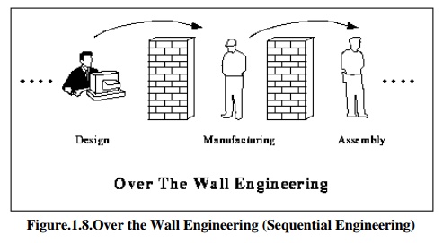
Figure.1.8.Over
the Wall Engineering (Sequential Engineering)
There are a lot of disadvantages
of the sequential engineering process. The designers are responsible for
creating a design that meets all the specified requirements. They are usually
not concerned with how the product will be manufactured or assembled. Problems
and inconsistencies in the designs are therefore, detected when the product
reaches into the later phases of its life-cycle. At this stage, the only
possible option is to send the product back for a re-design. The whole process
becomes iterative and it not until after a lot of re-designs has taken place
that the product is finally manufactured. Because of the large number of
changes, and hence iterations, the product's introduction to market gets
delayed. In addition, each re-design, re-work, re-assembly etc. incurs cost,
and therefore the resulting product is costlier than what it was originally
thought to be. The market share is lost because of the delay in product's
introduction to market, and customer faith is lost. All this is undesirable.
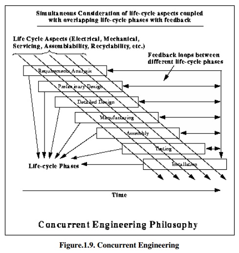
Concurrent Engineering is a
dramatically different approach to product development in which various
life-cycle aspects are considered simultaneously right from the early stages of
design. These life-cycle aspects include product's functionality,
manufacturability, testability, assimilability, maintainability, and everything
else that could be affected by the design.
In addition, various life-cycle
phases overlap each other, and there in no "wall" between these
phases. The completion of a previous life-cycle phase is not a pre-requisite
for the start of the next life-cycle phase. In addition, there is a continuous
feedback between these life-cycle phases so that the conflicts are detected as
soon as possible.
The concurrent approach results
in less number of changes during the later phases of product life-cycle,
because of the fact that the life-cycle aspects are being considered all
through the design. The benefits achieved are reduced lead times to market,
reduced cost, higher quality, greater customer satisfaction, increased market
share etc. Sequential engineering is the term used to describe the method of
production in a linear format. The different steps are done one after another,
with all attention and resources focused on that one task. After it is
completed it is left alone and everything is concentrated on the next task.
In concurrent engineering,
different tasks are tackled at the same time, and not necessarily in the usual
order. This means that info found out later in the process can be added to
earlier parts, improving them, and also saving a lot of time. Concurrent engineering
is a method by which several teams within an organization work simultaneously
to develop new products and services and allows a more stream lined approach.
The concurrent engineering is a non-linear product or project design approach
during which all phases of manufacturing operate at the same time -
simultaneously. Both product and process design run in parallel and occur in
the same time frame.
Product and process are closely
coordinated to achieve optimal matching of requirements for effective cost,
quality, and delivery. Decision making involves full team participation and
involvement. The team often consists of product design engineers, manufacturing
engineers, marketing personnel, purchasing, finance, and suppliers.
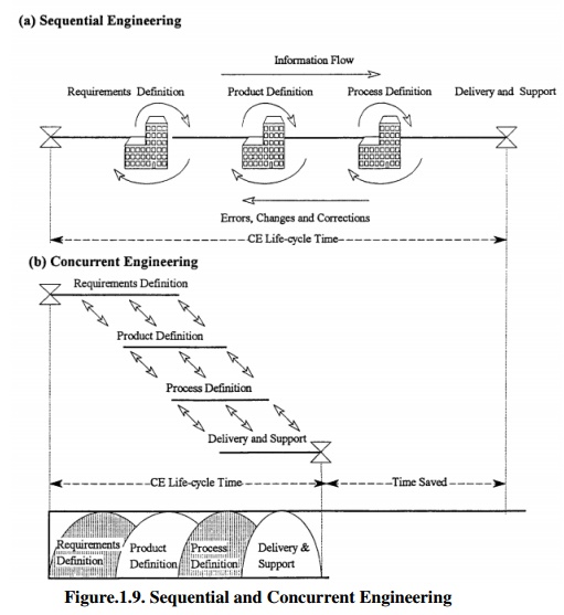
Figure.1.9. Sequential and
Concurrent Engineering
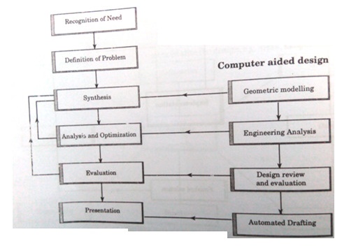
ROLE OF COMPUTERS IN DESIGN
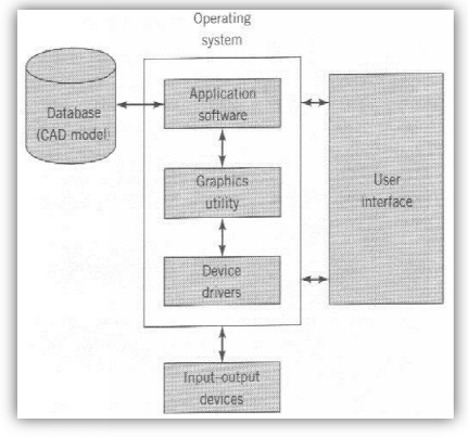
CAD SYSTEM ARCHIT ECTURE
COMPUTER AIDED E NGINEERING –
CAD/CAM
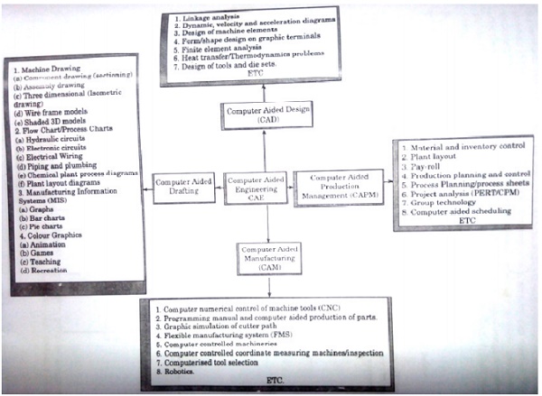
APPLICATION OF CO MPUTERS TO
DESIGN
• Modeling
of the D esign
• Engineering
design and analysis
• Evaluation
of Prot otype through Simulation and Testing
Drafting and Desig n Documentation
BENEFITS OF CAD
Productivity Improvem ent in Design Depends on
Comp lexity of drawing,
Degree of repetitiveness of features in the designed parts,
Degree of symmetr y in the parts,
Extensive use of li brary of user defined shapes and commonly
use d entities
Shorter Lead Times
Flexibility in Design
Design Analysis
Fewer Design Error
Standardization of Des ign, Drafting and
Documentation
7. Drawings
are more understandable
8. Improved
Procedures of Engineering Changes
9. Benefits
in Manufacturing :
a. Tool and
fixture design for manufacturing
b. Computer
Aided process planning
c. Preparation
of assembly lists and bill of materials
d. Computer
aided inspection
e. Coding
and classification of components
f. Production
planning and control
g. Preparation
of numerical control programs for manufacturing the parts on CNC machines
h. Assembly
sequence planning
REASONS FOR IMPLEMENTING CAD
• To
increase the productivity of the designer
• To
improve the Quality of Design
• To
improve Documentation
• To create
a Database for manufacturing
COMPUTER GRAPHICS or INTERACTIVE
COMPUTER GRAPHICS
Computer
Graphics is defined as creation, storage, and manipulation of pictures and
drawings by means of a digital computer
It is
an extremely effective medium for communication between people and computers
Computer
graphics studies the manipulation of visual and geometric information using
computational techniques
It
focuses on the mathematical and computational foundations of image generation
and processing rather than purely aesthetic issues
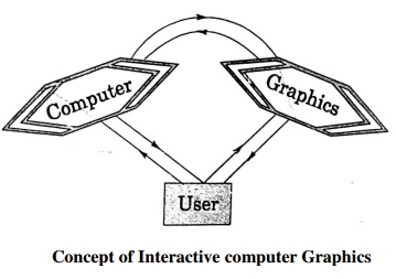
In Interactive Computer Graphics (ICG) the user interacts with
the compute and comprises the following important functions:
Modeling, which is concerned with the
description of an object in terms of its spatial coordinates,
lines, areas, edges, surfaces, and volume
Storage, which
is concerned with the storage of the model in the memory of the computer
Manipulation, which is used in the
construction of the model from basic primitives in combination
with Boolean algebra
Viewing, in the case the computer is
used to look at the model from a specific angle and presents on
its screen what it sees.
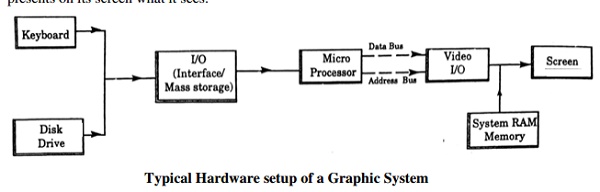
Typical
Hardware setup of a Graphic System
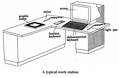
Work Station: A workstation comprises of
the devices that allow the user to create and design objects, using both
graphic and non-graphic instructions and data. A Stand alone workstation refers
to CAD workstations that can process data and output information independent of
other computer systems or workstations. It includes its own software, hardware,
and peripherals.
CO-ORDINATE SYSTEMS
A coordinate system is o ne which
uses one or more numbers, or coordinates, to uniquely determine the
position of a poi nt or other geometric element on a manifold
such as Euclidean space.
Common coordinate systems are:
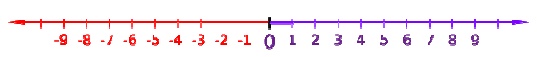
Number
line
The simplest exam ple of a coordinate system is the
identification of points on a line with real numbers using the number line. In
this system, an arbitrary point O (the origin) is chosen o n a given line. The
coordinate of a point P is de fined as the signed distance from O to P, where
the signed distance is the distance ta ken as positive or negative dependin g
on which side of the line P lies. Each point is given a unique coordinate and
each real number is the coordinate of a unique point
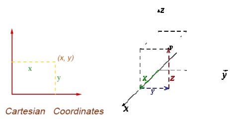
Cartesian coordin ate system [ (x,y) and (x,y,z) ]
Polar coordinate system (ρ,θ)
Another co mmon coordinate system
for the plane is the polar coordinate system. A point is chosen
as the pole and a ray from this point is taken as the polar axis.
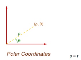
For a given angle θ, there
is a single line through the pole whose angle with the polar axis is θ (
measured counter clockwise from the axis to the line). Then there is a unique
point on this line whose signed distance from the or igin is r for given
number r. For a gi ven pair of coordinates (r, θ) there
is a single p oint, but any point is represented by many pairs of coordinates.
For example (r, θ), (r, θ+2π) and (−r,
θ+π) are all
po lar coordinates for the same point. The pole is represented by (0, θ) for any
value of
θ.
Cylindrical Coord inate systems
A cylindrical
coordinate system is a three-dimensional coordinate
system that specifies point positions by the distance from a chos en
reference axis, the direction from the axis relative to a chosen reference
directio n, and the distance from a chosen reference plane perpendicular to the
axis. The latter distance is given as a positive or n egative number depending
on which side of t he reference plane faces the point.
The origin of the system is the
point where all three coordinates can be given as zero. This is the intersection
between the reference plane and the axis.
The axis is variously called the
cylindrical or lon gitudinal axis, to differentiate it fro m the polar axis,
which is the ray that lies in th e reference plane, starting at the origin and
pointing in the reference direction.
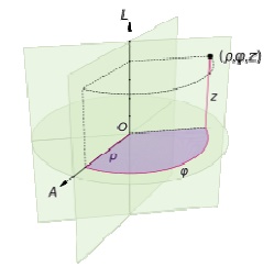
The distanc e from the axis may
be called the radial distance or radius, while the angular coord inate is
sometimes referred to as the angular position or as the azimuth.
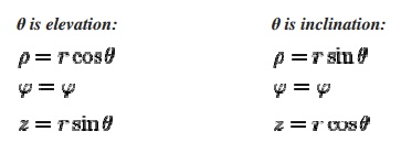
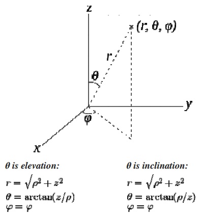
Spherical Coordi nate
systems
A spherical c oordinate system is a coordinate
system for three-dimensional space where the positi on of a point is specified
by three numbers: the radial distance of that point from a fixe d origin, its
polar angle measured from a fixe d zenith direction, and the azimuth angl e of
its orthogonal projection on a reference plane that passes through
the origin an d is orthogonal to the zenith, measured from a fixed reference
direction on that plane .
The radial dist ance is also
called the radius or radial coordinate. The polar angle may be called co-latitu
de, zenith angle, normal angle, or inclination angle
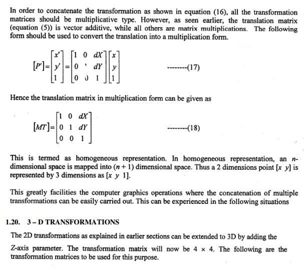
Homogeneous coo rdinate system
Three dimensional representation
of a two di mensional plane is called Homogeneo us Co-ordinates. The respective
system is called Homogeneous coordinate system.
2 – D DISPLAY CONTR OL FACILITIES
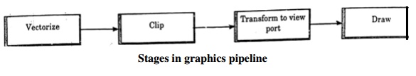
The essential steps for 2D graphics are:
1. Convert
the ge ometric representation of the model to lines (ter med Vectors)
2. Transform
the lines from the model coordinate system to the screen coordinate system
(termed windowing)
Select those lin es that are
within the part of the model that it is wished to display known as the c
lipping step
4. Instruct the display device to
draw the vectors The Stages in graphics pipeline are shown.
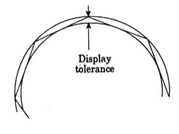
1. Vector
Generation
The aim of vector display of a
curve is to use sufficient vectors for the curve to appear smooth. The number
needed is controlled by the display tolerance, which is maximum deviation of
the vector representation from the true curve shape.
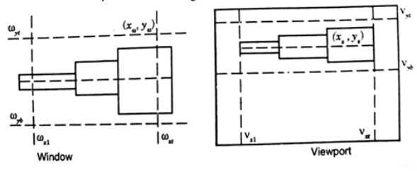
2.
Windowing Transformation
When it is necessary to examine in detail a part
of a picture being displayed, a window may be placed around the desired part
and the windowed area magnified to fill the whole screen and multiple views of
the model may also be shown on the same screen.
The window is a rectangular frame
or boundary through which the user looks onto the model. The viewport is the
area on the screen in which the contents of the window are to be presented as
an image.
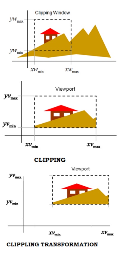
3. Clipping
Transformation
The clipping is an operation to plot part of a picture within
the given window of the plotting area and to discard the rest.
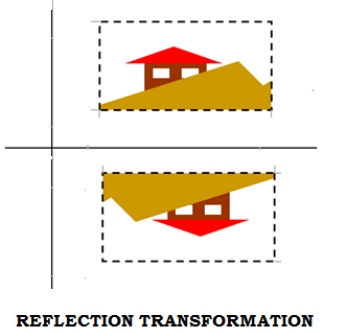
4. Reflection Transformation
Reflection
about any axis
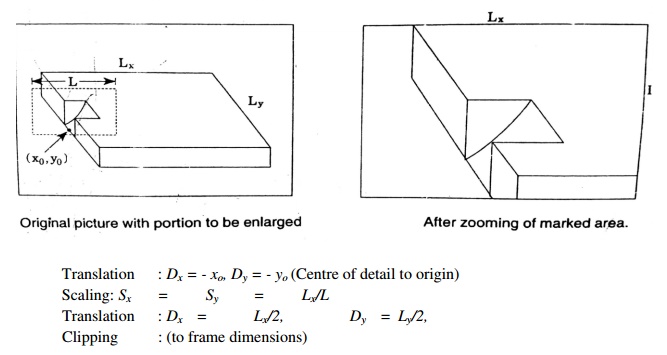
5. Zooming
This transformation is carried out to provide
enlarged or shrunk view of a picture detail
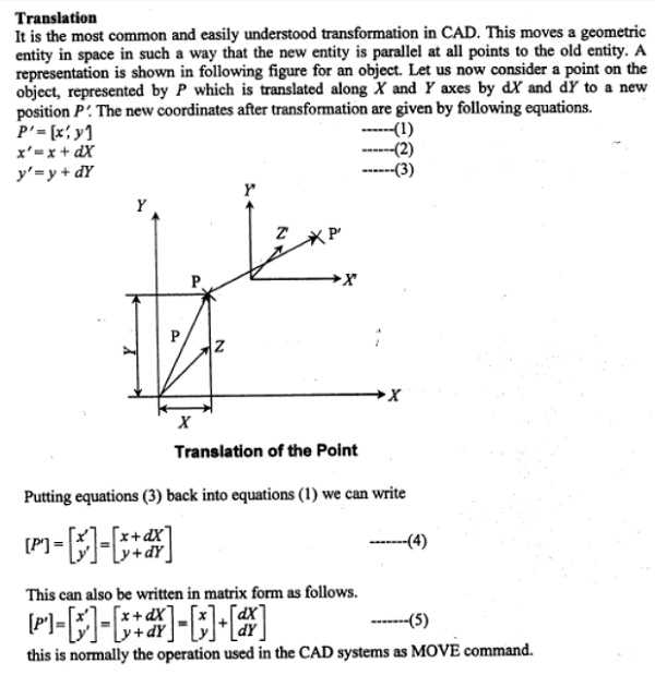
2– D TRANSFORMATIONS
i. Translation
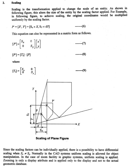
ii. Scaling
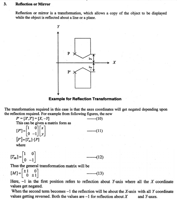
iii. Reflection
with mirror
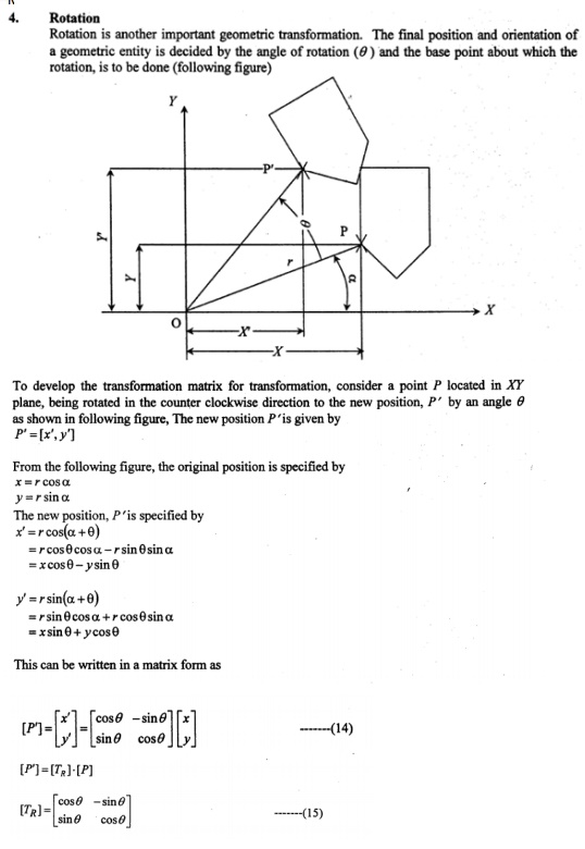
iv. Rotation
HOMOGENEOUS CO-ORDINATES
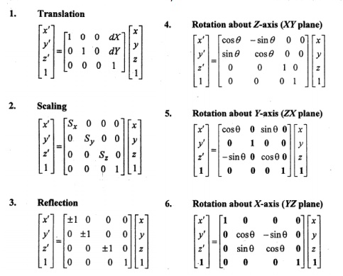
3 – D TRANSFORMATIONS
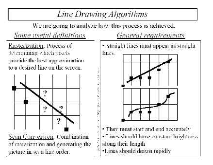
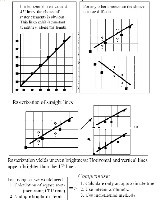
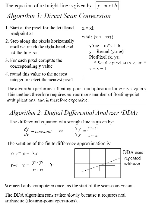
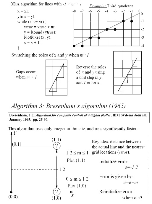
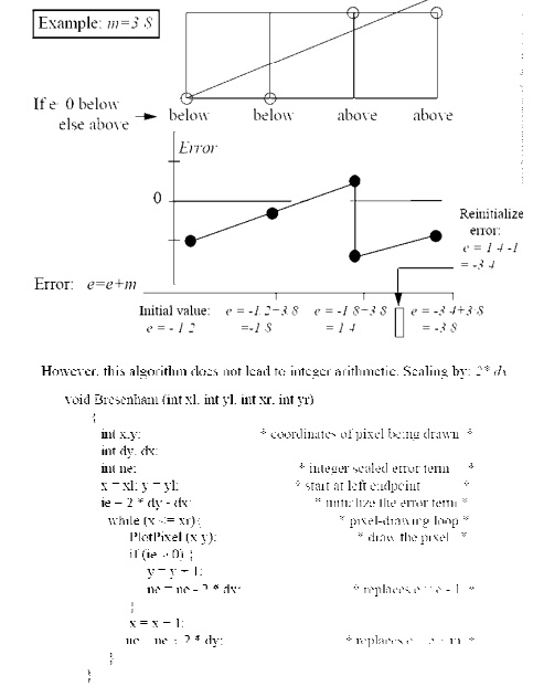
LINE DRAWING ALGOORITHMS
Related Topics