Chapter: Computer Networks
Data Communication
1. INTRODUCTION TO NETWORKS
1. Network Definition
A network can be defined as two or more computers connected together in such a way that they can share resources.
The purpose of a network is to share resources.
A resource may be:
A file
A folder
A printer
A disk drive
Or just about anything else that exists on a computer.
A network is simply a collection of computers or other hardware devices that are connected together, either physically or logically, using special hardware and software, to allow them to exchange information and cooperate. Networking is the term that describes the processes involved in designing, implementing, upgrading, managing and otherwise working with networks and network technologies
Advantages of networking.
Connectivity and Communication
Data Sharing
Hardware Sharing
Internet Access
Internet Access Sharing
Data Security and Management
Performance Enhancement and Balancing
Entertainment
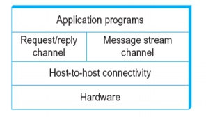
2. NETWORK ARCHITECTURE
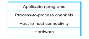
Layered system with alternative abstractions available at a given layer
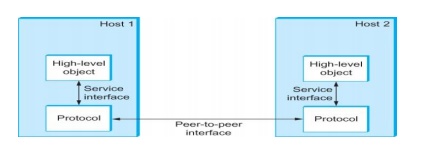
Protocols
o Protocol defines the interfaces between the layers in the same system and with the layers of peer system
o Building blocks of a network architecture
o Each protocol object has two different interfaces
§ service interface: operations on this protocol
§ peer-to-peer interface: messages exchanged with peer
o Term “protocol” is overloaded
§ specification of peer-to-peer interface
§ module that implements this interface
Interfaces
· Protocol Specification: prose, pseudo-code, state transition diagram
· Interoperable: when two or more protocols that implement the specification accurately
· IETF: Internet Engineering Task Force
3. OSI ARCHITECTURE
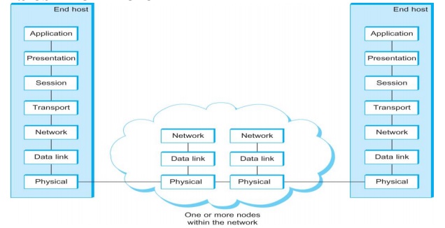
Description of Layers
Physical Layer
o Handles the transmission of raw bits over a communication link
Data Link Layer
o Collects a stream of bits into a larger aggregate called a frame
o Network adaptor along with device driver in OS implement the protocol in this layer
o Frames are actually delivered to hosts
Network Layer
o Handles routing among nodes within a packet-switched network
o Unit of data exchanged between nodes in this layer is called a packet
The lower three layers are implemented on all network nodes
Transport Layer
o Implements a process-to-process channel
o Unit of data exchanges in this layer is called a message
Session Layer
o Provides a name space that is used to tie together the potentially different transport streams that are part of a single application
Presentation Layer
o Concerned about the format of data exchanged between peers
Application Layer
o Standardize common type of exchanges
The transport layer and the higher layers typically run only on end-hosts and not on the intermediate switches and routers
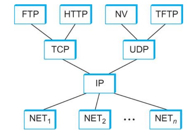
Internet Architecture
Defined by IETF
Three main features
o Does not imply strict layering. The application is free to bypass the defined transport layers and to directly use IP or other underlying networks
o An hour-glass shape – wide at the top, narrow in the middle and wide at the bottom. IP serves as the focal point for the architecture
o In order for a new protocol to be officially included in the architecture, there needs to be both a protocol specification and at least one (and preferably two) representative implementations of the specification
Application Programming Interface
o Interface exported by the network
o Since most network protocols are implemented (those in the high protocol stack) in software and nearly all computer systems implement their network protocols as part of the operating system, when we refer to the interface “exported by the network”, we are generally referring to the interface that the OS provides to its networking subsystem
o The interface is called the network Application Programming Interface (API)
o Socket Interface was originally provided by the Berkeley distribution of Unix
Now supported in virtually all operating systems
o Each protocol provides a certain set of services, and the API provides a syntax by which those services can be invoked in this particular OS
Socket
Socket Family
o PF_INET denotes the Internet family
o PF_UNIX denotes the Unix pipe facility
o PF_PACKET denotes direct access to the network interface (i.e., it bypasses the TCP/IP protocol stack)
o Socket Type
o SOCK_STREAM is used to denote a byte stream
o SOCK_DGRAM is an alternative that denotes a message oriented service, such as that provided by UDP
Creating a Socket
int sockfd = socket(address_family, type, protocol);
· The socket number returned is the socket descriptor for the newly created socket
· int sockfd = socket (PF_INET, SOCK_STREAM, 0);
· int sockfd = socket (PF_INET, SOCK_DGRAM, 0);
o The combination of PF_INET and SOCK_STREAM implies TCP
Bind
· Binds the newly created socket to the specified address i.e. the network address of the local participant (the server)
· Address is a data structure which combines IP and port
Listen
o Defines how many connections can be pending on the specified socket
Accept
o Carries out the passive open
o Blocking operation
o Does not return until a remote participant has established a connection
o When it does, it returns a new socket that corresponds to the new established connection and the address argument contains the remote participant’s address
Client
o Application performs active open
o It says who it wants to communicate with
Client invokes
o int connect (int socket, struct sockaddr *address, int addr_len)
Connect
o Does not return until TCP has successfully established a connection at which application is free to begin sending data
o Address contains remote machine’s address
4. NETWORK PERFORMANCE
·
Bandwidth
o
Width of the frequency band
o
Number of bits per second that can be transmitted
over a communication link
·
1 Mbps: 1 x 106 bits/second = 1x220
bits/sec
·
1 x 10⁻⁶ seconds to transmit each bit or
imagine that a timeline, now each bit occupies 1 micro second space.
·
On a 2 Mbps link the width is 0.5 micro second.
·
Smaller the width more will be transmission per
unit time.
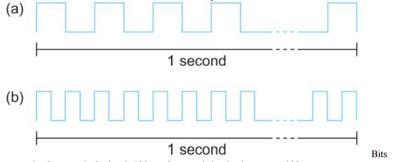
transmitted
at a particular bandwidth can be regarded as having some width:
a. bits
transmitted at 1Mbps (each bit 1 ÎĽs wide);
b. bits
transmitted at 2Mbps (each bit 0.5 ÎĽs wide).
·
Latency = Propagation + transmit + queue
·
Propagation = distance/speed of light
·
Transmit = size/bandwidth
·
One bit transmission => propagation is important
·
Large bytes transmission => bandwidth is
important Delay X Bandwidth
·
We think the channel between a pair of processes as
a hollow pipe
·
Latency (delay) length of the pipe and bandwidth
the width of the pipe
·
Delay of 50 ms and bandwidth of 45 Mbps
50 x 10-3 seconds x 45 x 106 bits/second
2.25 x 106 bits = 280 KB data.
Relative
importance of bandwidth and latency depends on application For large
file transfer, bandwidth is critical
For small messages (HTTP, NFS, etc.), latency is critical
Variance in latency (jitter) can also affect some applications (e.g.,
audio/video conferencing)
How many bits the sender must transmit before the first bit arrives at
the receiver if the sender keeps the pipe full
Takes another one-way latency to receive a response from the receiver
If the sender does not fill the pipe—send a whole delay × bandwidth
product’s worth of data before it stops to wait for a signal—the sender will
not fully utilize the network
Infinite bandwidth
RTT dominates
Throughput = TransferSize / TransferTime
TransferTime = RTT + 1/Bandwidth x TransferSize
Its all relative
1-MB file to 1-Gbps link looks like a 1-KB packet to 1-Mbps link
5. DIRECT LINK NETWORKS
o
Gives the upper bound to the capacity of a link in
terms of bits per second (bps) as a function of signal-to-noise ratio of the
link measured in decibels (dB).
o
C = Blog2(1+S/N)
§ Where B =
3300 – 300 = 3000Hz, S is the signal power, N the average noise.
§ The
signal to noise ratio (S/N) is measured in decibels is related to dB = 10 x log10(S/N).
If there is 30dB of noise then S/N = 1000.
§ Now C =
3000 x log2(1001) = 30kbps.
o
All practical links rely on some sort of
electromagnetic radiation propagating through a medium or, in some cases,
through free space
o
One way to characterize links, then, is by the medium
they use
§ Typically
copper wire in some form (as in Digital Subscriber Line (DSL) and coaxial
cable),
§ Another
important link characteristic is the frequency
§ Measured
in hertz, with which the electromagnetic waves oscillate
§ Distance
between the adjacent pair of maxima or minima of a wave measured in meters is
called wavelength
§ Speed of
light divided by frequency gives the wavelength.
§ Frequency
on a copper cable range from 300Hz to 3300Hz; Wavelength for 300Hz wave through
copper is speed of light on a copper / frequency
§ 2/3 x 3 x
108 /300 = 667 x 103 meters.
§ Placing
binary data on a signal is called encoding.
§ Modulation
involves modifying the signals in terms of their frequency, amplitude, and
phase.
§ Optical
fiber (as in both commercial fiber-to-the home services and many long-distance
links in the Internet’s backbone), or Air/free
space (for wireless links)
6. ENCODING
Problem
with NRZ
o
Baseline wander
§ The
receiver keeps an average of the signals it has seen so far
§ Uses the
average to distinguish between low and high signal
§ When a
signal is significantly low than the average, it is 0, else it is 1
§ Too many
consecutive 0’s and 1’s cause this average to change, making it difficult to
detect
Problem
with NRZ
o
Clock recovery
§ Frequent
transition from high to low or vice versa are necessary to enable clock
recovery
§ Both the
sending and decoding process is driven by a clock
§ Every
clock cycle, the sender transmits a bit and the receiver recovers a bit
§ The
sender and receiver have to be precisely synchronized
NRZI
o
Non Return to Zero Inverted
o
Sender makes a transition from the current signal
to encode 1 and stay at the current signal to encode 0
o
Solves for consecutive 1’s
Manchester
encoding
o
Merging the clock with signal by transmitting Ex-OR
of the NRZ encoded data and the clock
o
Clock is an internal signal that alternates from
low to high, a low/high pair is considered as one clock cycle
o
In Manchester encoding
§ 0: lowà high transition
§ 1: highà low transition
Problem
with Manchester encoding
o
Doubles the rate at which the signal transitions
are made on the link
§ Which
means the receiver has half of the time to detect each pulse of the signal
o
The rate at which the signal changes is called the
link’s baud rate
o
In Manchester the bit rate is half the baud rate
4B/5B
encoding
§ Insert
extra bits into bit stream so as to break up the long sequence of 0’s and 1’s
§ Every
4-bits of actual data are encoded in a 5- bit code that is transmitted to the
receiver
§ 5-bit
codes are selected in such a way that each one has no more than one leading
§ 0(zero)
and no more than two trailing 0’s.
§ No pair
of 5-bit codes results in more than three consecutive 0’s
7. FRAMING
§ We are
focusing on packet-switched networks, which means that blocks of data (called frames at this level), not bit streams,
are exchanged between nodes.
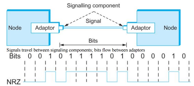
§ It is the
network adaptor that enables the nodes to exchange frames.
§ When node
A wishes to transmit a frame to node B, it tells its adaptor to transmit a
frame from the node’s memory. This results in a sequence of bits being sent
over the link.
§ The
adaptor on node B then collects together the sequence of bits arriving on the
link and deposits the corresponding frame in B’s memory.
§ Recognizing
exactly what set of bits constitute a frame—that is, determining where the
frame begins and ends—is the central challenge faced by the adaptor
§ Byte-oriented
Protocols
To view each frame as a collection of bytes
(characters) rather than bits
BISYNC (Binary Synchronous Communication) Protocol
Developed by IBM (late 1960)
DDCMP (Digital Data Communication Protocol)
Used in DECNet
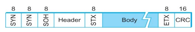
§ BISYNC –
sentinel approach
Frames
transmitted beginning with leftmost field
Beginning
of a frame is denoted by sending a special SYN (synchronize) character
Data
portion of the frame is contained between special sentinel character STX (start
of text) and ETX (end of text)
SOH :
Start of Header
DLE : Data
Link Escape
·
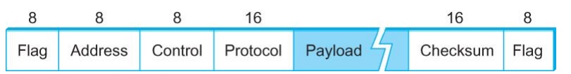
PPP Frame Format
Recent
PPP which is commonly run over Internet links uses sentinel approach
·
Special start of text character denoted as Flag
·
0 1 1 1 1 1 1 0
·
Address, control : default numbers
·
Protocol for demux : IP / IPX
·
Payload : negotiated (1500 bytes)
·
Checksum : for error detection
Byte-counting
approach
o
DDCMP
o
count : how
many bytes are contained in the frame body
o
If count
is corrupte
§ Framing
error
·
Bit-oriented Protocol
o
HDLC : High Level Data Link Control
§ Beginning
and Ending Sequences
0 1 1 1 1
1 1 0
HDLC Protocol
On the sending side, any time five consecutive 1’s
have been transmitted from the body of the message (i.e. excluding when the
sender is trying to send the distinguished 01111110 sequence)
The sender inserts 0 before transmitting the next
bit
HDLC Protocol
On the receiving side
5 consecutive 1’s
Next bit 0 : Stuffed, so discard it
1 :
Either End of the frame marker
Or Error has been introduced in the bitstream Look at the next bit
If 0 (
01111110 ) Ă End of
the frame marker
If 1 (
01111111 ) Ă Error,
discard the whole frame
The
receiver needs to wait for next 01111110 before it can start receiving again
8. ERROR DETECTION
Bit
errors are introduced into frames
Because
of electrical interference and thermal noises
Detecting
Error
Correction
Error
Two
approaches when the recipient detects an error
Notify
the sender that the message was corrupted, so the sender can send again.
If the
error is rare, then the retransmitted message will be error-free
Using
some error correct detection and correction algorithm, the receiver
reconstructs the message
Common
technique for detecting transmission error
CRC
(Cyclic Redundancy Check)
Used in
HDLC, DDCMP, CSMA/CD, Token Ring
Other
approaches
Two
Dimensional Parity (BISYNC)
Checksum
(IP)
Basic
Idea of Error Detection
To add
redundant information to a frame that can be used to determine if errors have
been introduced
Imagine
(Extreme Case)
Transmitting
two complete copies of data
n Identical
Ă No error
n Differ Ă Error
n Poor
Scheme ???
n n bit
message, n bit redundant information
n Error can
go undetected
In
general, we can provide strong error detection technique
n k
redundant bits, n bits message, k << n
n In
Ethernet, a frame carrying up to 12,000 bits of data requires only 32-bit CRC
Extra
bits are redundant
They add
no new information to the message
Derived
from the original message using some algorithm
Both the
sender and receiver know the algorithm
Sender Receiver Receiver computes r using m If they match, no error
9. TRANSMISSION
CRC is
used to detect errors.
Some
error codes are strong enough to correct errors.
The
overhead is typically too high.
Corrupt
frames must be discarded.
A
link-level protocol that wants to deliver frames reliably must recover from
these discarded frames.
This is
accomplished using a combination of two fundamental mechanisms
Acknowledgements
and Timeouts
An acknowledgement (ACK for short) is a
small control frame that a protocol sends back to its peer saying that it has
received the earlier frame.
A control
frame is a frame with header only (no data).
The
receipt of an acknowledgement
indicates to the sender of the original frame that its frame was successfully
delivered.
If the
sender does not receive an acknowledgment
after a reasonable amount of time, then it retransmits the original frame.
The
action of waiting a reasonable amount of time is called a timeout.
The
general strategy of using acknowledgements
and timeouts to implement reliable
delivery is sometimes called Automatic Repeat reQuest (ARQ).
Stop and Wait Protocol
Idea of
stop-and-wait protocol is straightforward
After
transmitting one frame, the sender waits for an acknowledgement before
transmitting the next frame.
If the
acknowledgement does not arrive after a certain period of time, the sender
times out and retransmits the original frame
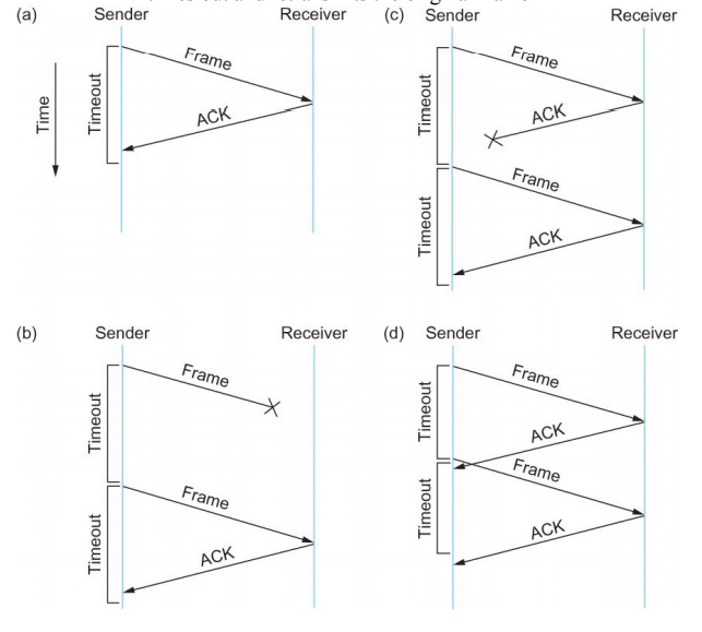
If the
acknowledgment is lost or delayed in arriving
The
sender times out and retransmits the original frame, but the receiver will think
that it is the next frame since it has correctly received and acknowledged the
first frame
As a
result, duplicate copies of frames will be delivered
How to
solve this
Use 1 bit
sequence number (0 or 1)
When the
sender retransmits frame 0, the receiver can determine that it is seeing a
second copy of frame 0 rather than the first copy of frame 1 and therefore can
ignore it (the receiver still acknowledges it, in case the first
acknowledgement was lost)
The
sender has only one outstanding frame on the link at a time
This may be far below the link’s capacity
Consider a 1.5 Mbps link with a 45 ms RTT
The link has a delay bandwidth product of 67.5 Kb or approximately 8 KB
Since the sender can send only one frame per RTT and assuming a frame size of 1
KB
Maximum Sending rate
Bits per frame Time per frame = 1024 8 0.045 = 182 Kbps Or about one-eighth of the link’s capacity
To use the link fully, then sender should transmit up to eight frames before having to wait for an acknowledgement
Sliding Window Protocol
Sender assigns a sequence number denoted as SeqNum to each frame.
Assume it
can grow infinitely large
Sender
maintains three variables
Sending
Window Size (SWS)
Upper
bound on the number of outstanding (unacknowledged) frames that the sender can
transmit
Last
Acknowledgement Received (LAR)
Sequence
number of the last acknowledgement received
Last
Frame Sent (LFS)
Sequence
number of the last frame sent
When an
acknowledgement arrives
the
sender moves LAR to right, thereby allowing the sender to transmit another
frame
Also the
sender associates a timer with each frame it transmits
It
retransmits the frame if the timer expires before the ACK is received
Note that
the sender has to be willing to buffer up to SWS frames
Receiver
maintains three variables
Receiving
Window Size (RWS)
Upper
bound on the number of out-of-order frames that the receiver is willing to
accept
Largest
Acceptable Frame (LAF)
Sequence
number of the largest acceptable frame
Last
Frame Received (LFR)
Sequence
number of the last frame received
Receiver
also maintains the following invariant
LAF – LFR ≤ RWS
If SeqNum ≤ LFR or SeqNum > LAF
Discard
it (the frame is outside the receiver window)
If LFR
< SeqNum ≤ LAF
Accept it
Now the
receiver needs to decide whether or not to send an ACK
Let
SeqNumToAck
Denote
the largest sequence number not yet acknowledged, such that all frames with
sequence number less than or equal to SeqNumToAck have been received
The
receiver acknowledges the receipt of SeqNumToAck even if high-numbered packets
have been received
This
acknowledgement is said to be cumulative.
The
receiver then sets
LFR =
SeqNumToAck and adjusts
LAF = LFR
+ RWS
For example, suppose LFR = 5 and RWS = 4
(i.e. the last ACK that the receiver sent was for seq. no. 5)
LAF = 9
If frames 7 and 8 arrive, they will be buffered because they are within the receiver window
But no ACK will be sent since frame 6 is yet to arrive Frames 7 and 8 are out of order
Frame 6 arrives (it is late because it was lost first time and had to be retransmitted)
Now Receiver Acknowledges Frame 8 and bumps LFR to 8
and LAF to 12
10. ETHERNET
Most
successful local area networking technology of last 20 years.
Developed
in the mid-1970s by researchers at the Xerox Palo Alto Research Centers (PARC).
Uses
CSMA/CD technology
Carrier
Sense Multiple Access with Collision Detection.
A set of
nodes send and receive frames over a shared link.
Carrier
sense means that all nodes can distinguish between an idle and a busy link.
Collision
detection means that a node listens as it transmits and can therefore detect
when a frame it is transmitting has collided with a frame transmitted by
another node.
Uses
ALOHA (packet radio network) as the root protocol
Developed
at the University of Hawaii to support communication across the Hawaiian
Islands.
For ALOHA
the medium was atmosphere, for Ethernet the medium is a coax cable.
DEC and
Intel joined Xerox to define a 10-Mbps Ethernet standard in 1978.
This
standard formed the basis for IEEE standard 802.3
More
recently 802.3 has been extended to include a 100-Mbps version called Fast
Ethernet and a 1000-Mbps version called Gigabit Ethernet.
An
Ethernet segment is implemented on a coaxial cable of up to 500 m.
This
cable is similar to the type used for cable TV except that it typically has an
impedance of 50 ohms instead of cable TV’s 75 ohms.
Hosts
connect to an Ethernet segment by tapping into it.
A
transceiver (a small device directly attached to the tap) detects when the line
is idle and drives signal when the host is transmitting.
The
transceiver also receives incoming signal.
The
transceiver is connected to an Ethernet adaptor which is plugged into the host.
The
protocol is implemented on the adaptor.
Multiple
Ethernet segments can be joined together by repeaters.
A repeater is a device that forwards
digital signals.
No more
than four repeaters may be positioned between any pair of hosts.
An
Ethernet has a total reach of only 2500 m.
Any
signal placed on the Ethernet by a host is broadcast over the entire network
Signal is
propagated in both directions.
Repeaters
forward the signal on all outgoing segments.
Terminators
attached to the end of each segment absorb the signal.
Ethernet
uses Manchester encoding scheme.
New
Technologies in Ethernet
Instead
of using coax cable, an Ethernet can be constructed from a thinner cable known
as 10Base2 (the original was 10Base5)
10 means
the network operates at 10 Mbps
Base
means the cable is used in a baseband system
2 means
that a given segment can be no longer than 200 m
New
Technologies in Ethernet
Another
cable technology is 10BaseT
T stands
for twisted pair
Limited
to 100 m in length
With
10BaseT, the common configuration is to have several point to point segments
coming out of a multiway repeater, called Hub
Access
Protocol for Ethernet
The
algorithm is commonly called Ethernet’s Media Access Control (MAC).
It is
implemented in Hardware on the network adaptor.
Frame
format
Preamble
(64bit): allows the receiver to synchronize with the signal (sequence of
alternating 0s and 1s).
Host and
Destination Address (48bit each).
Packet
type (16bit): acts as demux key to identify the higher level protocol.
Data (up
to 1500 bytes)
Minimally
a frame must contain at least 46 bytes of data.
Frame
must be long enough to detect collision.
CRC
(32bit)
Ethernet
Addresses
Each host
on an Ethernet (in fact, every Ethernet host in the world) has a unique
Ethernet Address.
The
address belongs to the adaptor, not the host.
It is
usually burnt into ROM.
Ethernet
addresses are typically printed in a human readable format
As a
sequence of six numbers separated by colons.
Each
number corresponds to 1 byte of the 6 byte address and is given by a pair of
hexadecimal digits, one for each of the 4-bit nibbles in the byte
Leading
0s are dropped.
For
example, 8:0:2b:e4:b1:2 is
00001000
00000000 00101011 11100100 10110001 00000010
To ensure
that every adaptor gets a unique address, each manufacturer of Ethernet devices
is allocated a different prefix that must be prepended to the address on every
adaptor they build
AMD has
been assigned the 24bit prefix 8:0:20
11. RINGS
A ring
toplogy network developed in the late 1960s. Supported mainly by IBM. Pushed
into the background by Ethernet in the 1990s.
a LAN
protocol which resides at the data link layer (DLL) of the OSI model
Shielded Twisted Pair with unique hermaphroditic connectors (IBM “Type 1”)
or
Symmetric
pair. Speed:
– 4 Mbps (1985)
16 Mpbs
(1989, IBM Ring operation
When
nobody is transmitting a token circles.
When a
station needs to transmit data, it converts the token into a data frame.
When the
sender receives its own data frame, it converts the frame back into a token.
If an
error occurs and no token frame, or more than one, is present, a special
station
(“Active
Monitor”) detects the problem and removes and/or reinserts tokens as necessary.
The Abort
frame: used to abort transmission by the sending station
FDDI
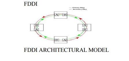
according to the osi-rm, fddi specifies layer 1
(physical layer) and part of layer 2 (data link control layer)
the physical layer handles the transmission of raw
bits over a communications link
the data link control (dlc) layer is responsible
for maintaining the integrity of information exchanged between two points
high bandwidth (10 times more than ethernet)
larger distances between fddi nodes because of very low attenuation (0.3 db/km) in fibers
improved signal-to-noise ratio because of no interference from external radio frequencies and electromagnetic noise
ber typical of fiber-optic systems (10^-11) is
substantially better than that in copper (10^-5) and microwave systems (10^-7)
very difficult to tap signals form a fiber cable
high cost of optical components required for
transmission/reception of signals (especially for single mode fiber networks)
more complex to implement than existing low speed
lan technologies such as ieee 802.3 and ieee 802.5
office automation at the desktop
backbones for factory automation
backend data center applications
campus lan interconnection
intercampus backbones or metropolitan area networks
(mans)
interconnection of private branch exchanges (pbxs)
workgroup and departmental lans
integrated transport for multimedia applications
12. SWITCHED NETWORKS

Datagram network is not either connection-oriented
or
connectionless.
Internet provides both connection-oriented (TCP)
and
connectionless
services (UDP) to apps.
mesh of
interconnected routers
the fundamental
question: how is data transferred through net?
circuit
switching: dedicated circuit per call: telephone net
packet-switching:
data sent thru net in discrete “chunks”
End-end
resources reserved for “call”
link
bandwidth, switch capacity
dedicated
resources: no sharing
circuit-like
(guaranteed) performance
call
setup required
network
resources (e.g., bandwidth) divided into “pieces”
pieces
allocated to calls
resource
piece idle if not used by owning call
(no sharing)
each
end-end data stream divided into packets
user A, B
packets share network resources
each
packet uses full link bandwidth
resources
used as needed
13. WIRELESS NETWORKS
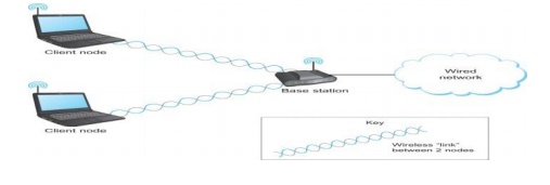
Wireless
links transmit electromagnetic signals
Radio,
microwave, infrared
Wireless
links all share the same “wire” (so to speak)
The
challenge is to share it efficiently without unduly interfering with each other
Most of
this sharing is accomplished by dividing the “wire” along the dimensions of
frequency and space
Exclusive
use of a particular frequency in a particular geographic area may be allocated
to an individual entity such as a corporation
These
allocations are determined by government agencies such as FCC (Federal
Communications Commission) in USA
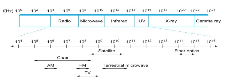
Specific
bands (frequency) ranges are allocated to certain uses.
Some
bands are reserved for government use
Other
bands are reserved for uses such as AM radio, FM radio, televisions, satellite
communications, and cell phones
Specific
frequencies within these bands are then allocated to individual organizations
for use within certain geographical areas.
Finally,
there are several frequency bands set aside for “license exempt” usage
Bands in
which a license is not needed
Devices
that use license-exempt frequencies are still subject to certain restrictions
The first
is a limit on transmission power
This
limits the range of signal, making it less likely to interfere with another
signal
For
example, a cordless phone might have a range of about 100 feet.
he second
restriction requires the use of Spread Spectrum technique
Idea is
to spread the signal over a wider frequency band
So as to
minimize the impact of interference from other devices
Originally
designed for military use
Frequency hopping
Transmitting
signal over a random sequence of frequencies
First
transmitting at one frequency, then a second, then a third…
The
sequence of frequencies is not truly random, instead computed algorithmically
by a pseudorandom number generator
The
receiver uses the same algorithm as the sender, initializes it with the same
seed, and is
Able to
hop frequencies in sync with the transmitter to correctly receive the frame
A second
spread spectrum technique called Direct
sequence
Represents
each bit in the frame by multiple bits in the transmitted signal.
For each
bit the sender wants to transmit
It
actually sends the exclusive OR of that bit and n random bits
The
sequence of random bits is generated by a pseudorandom number generator known
to both the sender and the receiver.
The
transmitted values, known as an n-bit
chipping code, spread the signal across a frequency band that is n times wider
Wireless
technologies differ in a variety of dimensions
How much
bandwidth they provide
How far
apart the communication nodes can be
Four
prominent wireless technologies
Bluetooth
Wi-Fi
(more formally known as 802.11)
WiMAX
(802.16)
3G
cellular wireless
14. BRIDGES
Bridges
and LAN Switches
Class of
switches that is used to forward packets between shared-media LANs such as
Ethernets
Known as
LAN switches
Referred
to as Bridges
Suppose
you have a pair of Ethernets that you want to interconnect
One
approach is put a repeater in between them
It might
exceed the physical limitation of the Ethernet
No more
than four repeaters between any pair of hosts
No more
than a total of 2500 m in length is allowed
An
alternative would be to put a node between the two Ethernets and have the node
forward frames from one Ethernet to the other
This node
is called a Bridge
A
collection of LANs connected by one or more bridges is usually said to form an
Extended LAN
Simplest
Strategy for Bridges
Accept
LAN frames on their inputs and forward them out to all other outputs
Used by
early bridges
Learning
Bridges
Observe
that there is no need to forward all the frames that a bridge receives
Broadcast
and Multicast
Forward
all broadcast/multicast frames
Current
practice
Learn
when no group members downstream
Accomplished
by having each member of group G send a frame to bridge multicast address with
G in source field
Limitation
of Bridges
Do not
scale
Spanning
tree algorithm does not scale
Broadcast
does not scale,Do not accommodate heterogeneity
Related Topics