Chapter: Computer Networks : Fundamentals & Link Layer
Error Detection and Correction: Its types
ERROR DETECTION
For
reliable communicati on errors must be detected and corrected. For error
detection we are using many mechanisms.
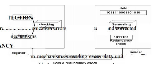
REDUNDANCY
One error
detection mechanism is sending every data unit twice. The receiving device then
would be able to do a bit for bit comparison between the two versions of the
data. Any discrepancy would indicate an er ror, and an appropriate correction
mechanism could be used.
But
instead of repeating the entire data stream, a shorter group of bits may be
appended to the end of each unit. This technique is called redundancy because
extra bits are redundant to the information. They are discarded as soon as the
accuracy of the transm ission has been determined.
TYPES
Four
types of redundancy checks are used in data communications. They are,
1. vertical
redundancy check (VRC)
2. longitudinal
r edundancy check (LRC)
3. cyclic
redund ancy check (CRC)
4. checksum
VERTICAL REDUNDANCY CHECK:
It is
also known as parity check. In this technique a redundant bit called a parity
bit is appended to every data unit so that the total number of 1s in the unit
includi ng the parity bit becomes even for even parity or odd for odd parity.
In even
parity, the data unit is passed through the even parity generator. It counts
the number of 1s in the data unit. If odd number of 1s, then it sets 1 in the
parity bit to make the number of 1s as even. If the data unit having even
number of 1s then it sets in the parity bit to maintain the number of 1s as
even. When it reaches its destination, the receiver puts all bits through an
even parity checking function. If it counts even number of 1s than there is no
error. Otherwise there is some error.
EXAMPLE:
The data
is : 01010110
The VRC
check : 010101100
In odd
parity, the data unit is passed through the odd parity generator. It counts the
number of 1s in the data unit. If even number of 1s, then it sets 1 in the
parity bit to make the number of 1s as odd. If the data unit having odd number
of 1s then it sets in the parity bit to maintain the number of 1s as odd. When
it reaches its destination, the receiver puts all bits through an odd parity
checking function. If it counts odd number of 1s than there is no error.
Otherwise there is some error.
EXAMPLE
The data
is: 01010110
The VRC
check: 01010111
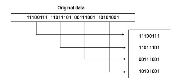
LONGITUDINAL REDUNDANCY CHECK
In this,
a block of bits is organized in a table (rows and columns). For example,
instead of sending a block of 32 bits, we organize them in a table made of four
roes and eight columns. We then calculate the parity bit for each column and
create a new row of eight bits which are the parity bits for the whole block
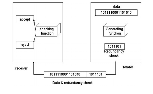
CYCLIC REDUNDANCY CHECK
CRC is
based on binary division. In this a sequence of redundant bits, called CRC
remainder is appended to the end of a data unit so that the resulting data unit
becomes exactly divisible by a second predetermined binary number. At its
destination, the incoming data unit is divided by the same number. If at this
step there is no reminder, the data unit is assumed to be intact and therefore
accepted. A remainder indicates that the data unit has been changed in transit
and therefore must be rejected.
Here, the
remainder is the CRC. It must have exactly one less bit than the divisor, and
appending it to the end of the data string must make the resulting bit sequence
exactly divisible by the divisor.
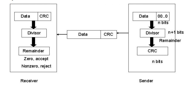
First, a
string of n-1 0s is appended to the data unit. The number of 0s is one less
than the number of bits in the divisor which is n bits. Then the newly
elongated data unit is divided by the divisor using a process called binary
division. The remainder is CRC. The CRC is replaces the appended 0s at the end
of the data unit.
The data
unit arrives at the receiver first, followed by the CRC. The receiver treats
whole string as the data unit and divides it by the same divisor that was used
to find the CRC remainder. If the remainder is 0 then the data unit is error
free. Otherwise it having some error and it must be discarded.
CHECKSUM
The error
detection method used by the higher layer protocols is called checksum. It
consists of two arts. They are,
1. checksum
generator
2. checksum
checker
Checksum Generator:
In the
sender, the checksum generator subdivides the data unit into equal segments of
n bits. These segments are added with each other by using one‟s complement arithmetic in such a
way that the total is also n bits long. That total is then complemented and
appended to the end of the data unit.
Checksum Checker:
The
receiver subdivides the data unit as above and adds all segments together and
complements the result. If the extended data unit is intact, the total value
found by adding the data segments and the checksum field should be zero.
Otherwise the packet contains an error and the receiver rejects it.
EXAMPLE
At the sender
Data unit: 10101001 00111001 10101001 00111001
Sum 1100010
Checksum 00011101
At the receiver
1)
Received
data: 10101001 00111001 00011101
10101001
00111001 00011101
Sum 11111111
Complement 00000000
It means
that the patter is ok.
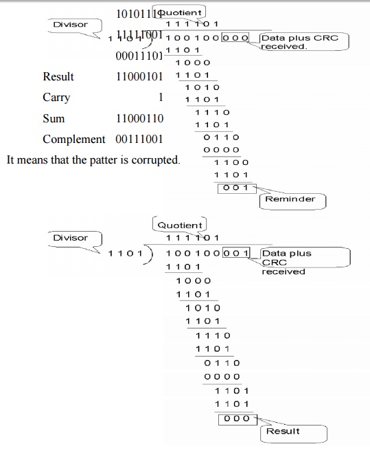
2)
Received
data: 1010111 111001 00011101
10101111
11111001
00011101 Result 11000101 Carry 1 Sum 11000110 Complement 00111001
It means
that the patter is corruptted.
ERROR CORRECTION
Error
correction is handled in two ways. In one, when an error is discovered, the
receiver can have the sender retransmit the entire data unit. In the other, a
receiver can use an error correcting code, which automatically corrects certain
errors.
Types of error correction:
1. Single
bit error correction
2. Burst bit
error correction
Single Bit Error Correction
To
correct a single bit error in an ASCII character, the error correction code
must determine which of the seven bits has changed. In this case we have to
determine eight different states: no error, error in position 1, error in
position 2, error in position 3, error in position 4, error in position 5,
error in position 6, error in position 7. It looks like a three bit redundancy
code should be adequate because three bits can show eight different states. But
what if an error occurs in the redundancy bits? Seven bits of data and three
bits of redundancy bits equal 10 bits. So three bits are not adequate.
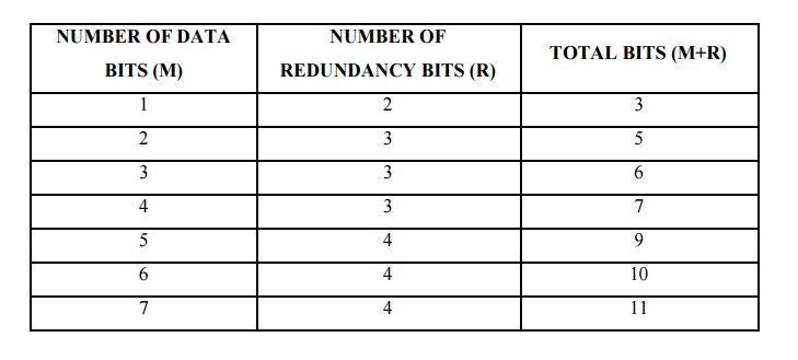
To
calculate the number of redundancy bits (r) required to correct a given number
of data bits (m) we must find a relationship between m and r.
If the
total number of bits in a transmittable unit is m+r then r must be able to
indicate at least m+r+1 different state. Of these, one state means no error and
m+r states indicate the location of an error in each of the m+r positions.
So m+r+1
state must be discoverable by r bits. And r bits can indicate 2r
different states. Therefore, 2r must be equal to or greater than
m+r+1;
2r >=m+r+1
Hamming Code:
The hamming code can be applied to data units of
any length and uses the relationship between data and redundancy bits.
Positions
of redundancy bits in hamming code
The combinations used to calculate each of the four
r values for a seven bit data sequence are as follows:
r1
:1,3,5,7,9,11
r2 :
2,3,6,7,10,11
r3 :
4,5,6,7
r4 :
8,9,10,11
Here, r1
bit is calculated using all bit positions whose binary representation includes
a 1 in the rightmost position (0001, 0011, 0101, 0111, 1001, and 1011). The r2
bit is calculated using all bit positions with a 1 in the second position
(0010, 0011, 0110, 0111, 1010 and 1011), and for r3 1 at third bit position
(0100, 0101, 0110 and 0111) for r4 1 at fourth bit position (1000, 1001, 1010
and 1011).
Calculating the r Values:
In the
first step, we place each bit of the original character in its appropriate
positions in the 11 bit unit. Then, we calculate the even parities for the
various bit combinations. The parity value of each combination is the value of
the corresponding r bit. For example r1 is calculated to provide even parity
for a combination of bits 3, 5, 7, 9, 11.
Error Detection and Correction:
Example:
At the sender:
Data to
be sent: 1001101
Redundancy
bit calculation:
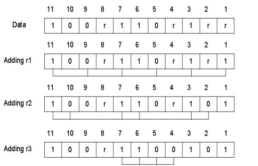
Data sent
with redundancy bits: 10011100101
During transmission:
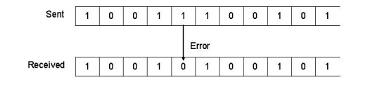
At the receiver:
The
receiver takes the transmission and recalculates four new r values using the
same set of bits used by the sender plus the relevant parity (r) bit for each
set. Then it assembles the new parity values into a binary number in order of r
position (r8, r4, r2, r1).
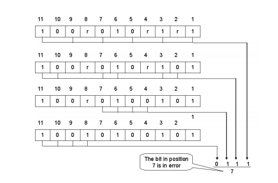
Once the
bit is identified, the receiver can reverse its value and correct the error.
Burst Bit Error Correction:
A hamming
code can be designed to correct burst errors of certain length. The number of
redundancy bits required to make these corrections, however, is dramatically
higher than that required for single bit errors. To correct double bit errors,
for example, we must take into consideration that the two bits can be a
combination of any two bits in the entire sequence. Three bit correction means
any three bits in the entire sequence and so on.
Related Topics