Chapter: Computer Networks : Fundamentals & Link Layer
Layering and Protocol
LAYERING AND PROTOCOL
To reduce
the complexity of getting all the functions maintained by one a new technique
called layering technology was introduced. In this, the architecture contains
several layers and each layer is responsible for certain functions. The general
idea is that the services offered by underlying hardware, and then add a
sequence of layers, each providing a higher level of service. The services
provided at the higher layers are implemented in terms of the services provided
by the lower layers. A simple network has two layers of abstraction sandwiched
between the application program and the underlying hardware.
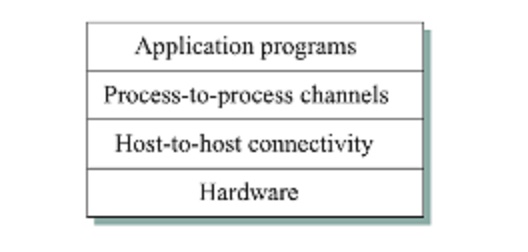
The layer
immediately above the hardware in this case might provide host to host
connectivity, and the layer above it builds on the available host to host
communication service and provides support for process to process channels.
Features
of layering are: 1. It decomposes the problem of building a network into more
manageable components. 2. It provides a more modular design. Addition of new
services and modifications are easy to implement.
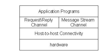
In
process to process channels, they have two types of channels. One for reque
st\reply service and the other for messag e stream service.
A
protocol provides a communication service that higher level objects use to
exchange message. Each protocol defines two different interfaces. First it
defines a serv ice interface to other objects on the same syste m that want to
use its communication services. This interface defines the operations that
local objects can perform on the protocol. Second a protocol defines a peer
interface to its counterpart on another machine. It defines the form and
meaning of message exchanged between protocol peers to implement the
communication service.
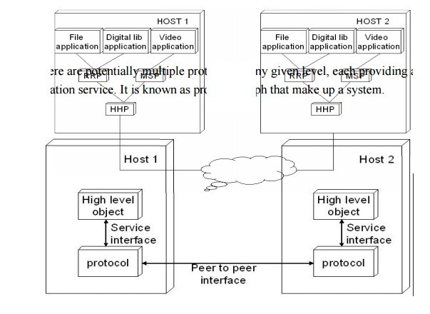
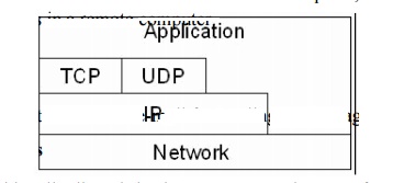
There are
potentially multiple protocols at any given level, each providing a different
communication service. It is known as protocol graph that make up a system.
ISO / OSI MODEL:
ISO
refers International Standards Organization was established in 1947, it is a
multinational body dedicated to worldwide agreement on international standards.
OSI
refers to Open System Interconnection that covers all aspects of network
communication. It is a standard of ISO.
Here open system is a model that allows any
two different systems to communicate regardless of their underlying
architecture. Mainly, it is not a protocol it is just a model.
OSI MODEL
The open
system interconnection model is a layered framework. It has seven separate but
interrelated layers. Each layer having unique responsibilities.
ARCHITECTURE
The
architecture of OSI model is a layered architecture. The seven layers are,
1. Physical
layer
2. Datalink
layer
3. Network
layer
4. Transport
layer
5. Session
layer
6. Presentation
layer
7. Application
layer
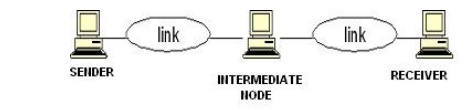
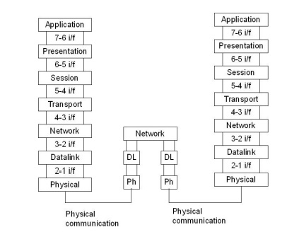
The figure shown below shows the layers involved when a message sent
from A to B pass through some intermediate devices.
Both the
devices A and B are formed by the framed architecture. And the intermediate
nodes only having the layers are physical, Datalink and network. In every
device each layer gets the services from the layer just below to it. When the
device is connected to some other device the layer of one device communicates
with the corresponding layer of another device. This is known as peer to peer process.
Each
layer in the sender adds its own information to the message. This information
is known is header and trailers. When the information added at
the beginning of the data is known as header. Whereas added at the end then it
called as trailer. Headers added at layers 2, 3, 4, 5, 6. Trailer added at
layer 2.
Each
layer is connected with the next layer by using interfaces. Each interface
defines what information and services a layer must provide for the layer above
it.
ORGANIZATION OF LAYERS
The seven
layers are arranged by three sub groups.
1. Network
Support Layers
2. User
Support Layers
3. Intermediate
Layer
Network Support Layers:
Physical,
Datalink and Network layers come under the group. They deal with the physical
aspects of the data such as electrical specifications, physical connections,
physical addressing, and transport timing and reliability.
User Support Layers:
Session, Presentation and Application layers comes under the group. They
deal with the interoperability between the software systems.
Intermediate Layer
The transport layer is the intermediate layer between the network
support and the user support layers.
FUNCTIONS OF THE LAYERS
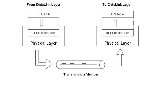
PHYSICAL LAYER
The physical
layer coordinates the functions required to transmit a bit stream over a
physical medium. It deals with the mechanical and electrical specifications of
the interface and the transmission medium.
The
functions are,
1. Physical
Characteristics Of Interfaces and Media:
It defines the
electrical and mechanical characteristics of the interface and the media.
It defines the
types of transmission medium
2.
Representation of Bits
To transmit the
stream of bits they must be encoded into signal.
It defines the
type of encoding weather electrical or optical.
3. Data
Rate
It defines the transmission rate i.e. the
number of bits sent per second.
4. Synchronization
of Bits
The sender and receiver must be synchronized
at bit level.
5. Line
Configuration
It defines the
type of connection between the devices.
Two types of
connection are,
1. point to point
2. multipoint
6. Physical
Topology
It defines how devices
are connected to make a network.
Five topologies
are,
1. mesh
2. star
3. tree
4. bus
5. ring
7. Transmission
Mode
It defines the direction of
transmission between devices.
Three
types of transmission are,
1. simplex
2. half
duplex
3. full
duplex
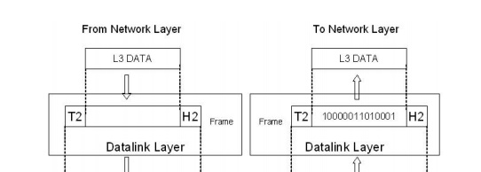
DATALINK LAYER
Datalink
layer responsible for node-to-node delivery.
The
responsibilities of Datalink layer are,
1. Framing
It divides the stream of bits received
from network layer into manageable data
units called frames.
2. Physical
Addressing
It adds a header
that defines the physical address of the sender and the receiver.
If the sender and
the receiver are in different networks, then the receiver address is
the address of the device which connects the two networks.
3. Flow
Control
It imposes a flow
control mechanism used to ensure the data rate at the sender and the receiver
should be same.
4.
Error
Control
* To
improve the reliability the Datalink layer adds a trailer which contains the
error control mechanism like CRC, Checksum etc.
5.
Access
Control
* When two
or more devices connected at the same link, then the Datalink layer used to
determine which device has control over the link at any given time.
NETWORK LAYER
When the
sender is in one network and the receiver is in some other network then the
network layer has the responsibility for the source to destination delivery.
The
responsibilities are,
1.
Logical
Addressing
* If a
packet passes the network boundary that is when the sender and receiver are
places in different network then the network layer adds a header that defines
the logical address of the devices.
2. Routing
* When more than one networks connected and to
form an internetwork, the
connecting
devices route the packet to its final destination.
* Network
layer provides this mechanism.
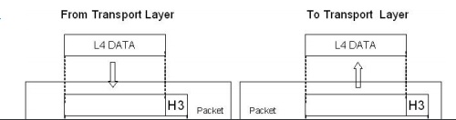
TRANSPORT LAYER
The
network layer is responsible for the end to end delivery of the entire message.
It ensures that the whole message arrives in order and intact. It ensures the
error control and flow control at source to destination level.

The responsibilities are,
1. Service
point Addressing
A single computer
can often run several programs at the same time.
The transport
layer gets the entire message to the correct process on that computer.
It adds a header
that defines the port address which used to identify the exact process on the
receiver.
2. Segmentation
and Reassembly
A message is
divided into manageable units called as segments.
Each segment
is reassembled after
received that information
at the receiver end.
To make
this efficient each segment contains a sequence number.
3. Connection
Control
The transport
layer creates a connection between the two end ports.
*
It involves three steps. They are,
1. connection
establishment
2. data
transmission
3. connection
discard
4.
Flow
Control
Flow
control is performed at end to end level
5.
Error
Control
* Error
control is performed at end to end level.
SESSION LAYER
It acts
as a dialog controller. It establishes, maintains and synchronizes the
interaction between the communication devices.
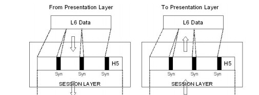
The responsibilities are,
1. Dialog
Control
The session layer
allows two systems to enter into a dialog.
It allows the
communication between the devices.
2. Synchronization
It adds a synchronization points into
a stream of bits.
PRESENTATION LAYER
The presentation layer is responsible for the semantics and the syntax
of the information exchanged.
The
responsibilities are,
1. Translation
* Different systems use different encoding
systems.
* The presentation layer is responsible for
interoperability between different
systems.
* The
presentation layer t the sender side translates the information from the sender
dependent format to a common format. Likewise, at the receiver side
presentation layer translate the information from common format to receiver
dependent format.
2. Encryption
* To ensure security encryption/decryption is
used
* Encryption means transforms
the original information to another form
* Decryption means retrieve the original
information from the encrypted
data
3.
Compression
* It used
to reduce the number of bits to be transmitted.
APPLICATION LAYER
The application la yer enables the user to access the network. It
provides interfaces between the users to the network.
The responsibilities are,
1. Network
Virtual Terminal
It is a
software v ersion of a physical terminal and allows a us er to log on to a
remote host.
2. File
Transfer, Access, a nd Management
It allows a
user to access files in a remote computer, retrieve files, and manage or
control files in a remote computer.
3. Mail
Services
It provides the
ba sis for e-mail forwarding and storage.
4. Directory
Services
It
provides distri buted database sources and access for global i nformation about
various objects an d services.
Related Topics