Chapter: Computer Networks : Media Access & Internetworking
IP(Internet Protocol)
IP(INTERNET PROTOCOL)
An
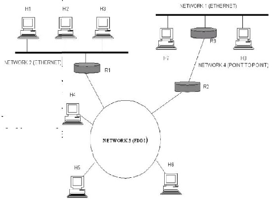
internetwork is often referred to as a network of networks because it is made
up of lots of smaller networks. The n odes that interconnect the networks are
called routers. They are also sometimes called gateways, but since this term
has several other connotations, we restrict our usage to router. The internet
protocol is the key tool used today to build scalable, heterogeneous
internetwork.
SERVICE MODEL:
The main
concern in defining a service model for an internetwork is that we can provide
a host-to-host service o nly if this service can somehow be provided over each
of the underlying physical networks. For Example, it would be no good deciding
that our internetwork service model was going to pro vide guaranteed delivery
of every packet in 1 m s or less if there were underlying network techno logies
that could arbitrarily delay packets.
The IP
service model can be thought of as having two parts: an ad dressing scheme,
which provides a way to identify all hosts in the internetwork, and a datagram
(connectionless) model of data delivery. This service model is sometimes called
best effort bec ause, although IP makes every effort to delivery da tagram, it
makes no guarantees.
DATAGRAM DELIVERY:
A
datagram is a type of packe t that happens to be sent in a connectionles s
manner over a network. Every datagram carries enough information to let network
forward the packet to its correct destination; there is no need for any advance
setup mechanism to tell the network what to do when the packet arrives. The
network makes its best effort to get it to the desired destination. The
best-effort part means that if something goes wrong and the packet gets lost,
corrupted, misdelivered,or in any way fails to reach its intended destination,
the network does nothing-it made its best effort, and that is all it had to do.
It does not make any attempt to recover from the failure. This is sometimes
called an unreliable service.
PACKET FORMAT:
The IP
datagram, like most packets, consists of a header followed by a number of
bytes of
data.
The
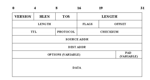
Version field specifies the version of IP. The current version of IP is 4, and
it is sometimes called IPv4^2.putting this field right at the start of the
datagram makes it easy for everything else in the packet format to be redefined
in subsequent versions; the header processing software starts off by looking at
the version and then branches off to process the rest of the packet according
to the appropriate format.
The next
field, HLEN, specifies the length of the header in 32-bit words. When there are
no options, which is most of the time, the header is 5 words (20 bytes) long.
The 8_bit type of service (TOS) field has had a number of different definitions
over the years, but its basic function is to allow packets to be treated
differently based on application needs. For example, the TOS value might
determine whether or not a packet should be placed in a special queue that
receives low delay.
The next
16-bit of the header contain the Length of the datagram, including the header.
Unlike the HLEN field, the Length field counts bytes rather than words. Thus,
the maximum size of an IP datagram is 65,535 bytes. The physical network, over
which IP is running, however, may not support such long packets. For this
reason, IP supports a fragmentation and reassembly process, the second word of
the header contains information about fragmentation. The next byte is the time
to live (TTL) field. The intent of the field is to catch packets that have been
going around in routing loops and discard them, rather than let them consume
resources indefinitely.
The
Protocol field is simply a demultiplexing key that identifies the higher-level
protocol to which this packet should be passed. These are values defined for
TCP (6), UDP (17), and many other protocols that may sit above IP in the
protocol graph.
The
Checksum is calculated by considering the entire IP header as a sequence of
16-bit words, adding them up using ones complement arithmetic, and taking the
ones complement of the result.
The last
two required fields in the header are the SourceAddr and the DestinationAddr
for the packet. The latter is the key to datagram delivery: every packet
contains a full address for its intended destination so that forwarding
decisions can be made at each router. The source address is required tom allow
recipients to decide if they want to accept the packet and to enable them to
reply.
Finally,
there may be a number of options at the end of the header. The presence or
absence of options may be determined by examining the header length (HLen)
field. While options are used fairly rarely, a complete IP implementation must
handle them all.
FRAGMENTATION AND REASSEMBLY:
One of
the problems of providing a uniform host-to-host service model over a
heterogeneous collection of network is that each network technology tends to
have its own idea of how large a packet can be. For example, an Ethernet can
accept packets up to 1,500 bytes long, while FDDI packets may be 4,500 bytes
long.
This
leaves two choices for the IP service model: make sure that all IP datagram are
small enough to fit inside one packet on any network technology, or provide a
means by which packets can be fragmented and reassembled when they are too big
to go over a given network technology.
The
latter turns out to be a good choice, especially when you consider the fact
that new network technologies are always turning up, and IP needs to run over
all of them; this would make it hard to pick a suitably small bound on datagram
size.
This also
means that a host will not send needlessly small packets, which wastes
bandwidth and consumes processing resources by acquiring more headers per byte
of data sent. For example, two hosts connected to FDDI networks that are
interconnected by a point-to-point link would not need to send packets small
enough to fit on an Ethernet.
The
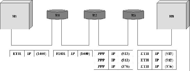
central idea here is that every network type has a maximum transmission unit
(MTU), which is the largest IP datagram that it can carry in a frame.
The
unfragmented packet has 1,400 bytes of data and a 20-byte IP header. When the
packet arrives at the R2, which has an MTU of 532 bytes, it has to be
fragmented. A 532-byte MTU leaves 512 bytes for data after the 20-byte IP
header , so the first fragment contains 512 bytes of data. The router sets the
M bit in the Flags field, meaning that there are more fragments to follow, and
it sets the offset to 0,since this fragmented contains the first part of the
original datagram.
The data
carried in the second fragment starts with the 513th byte of the
original data, so the Offset field in this header is set to 64,which is 512/8.
Why the division by 8? Because the designers of IP decided that fragmentation
should always happen on 8-byte boundaries, which means that the Offset field
counts 8-byte chunks, not bytes. The third fragment contains the last 376 bytes
of data, and the offset is now 2*512/8=128.since this is the last fragment, the
M bit is not set.

GLOBAL ADRESSES:
Global
uniqueness is the first property that should be provided in an addressing
scheme. Ethernet addresses are globally unique but not sufficient to address
entire network. And also they are flat that is no structure in addressing.
IP
addresses are hierarchical. They made up of two parts, they are a network part
and a host part. The network part identifies the network to which the host is
connected. All hosts which are connected to the same network have same network
part in their IP address. The host part then identifies each host on the particular
network.
The
routers are host but they are connected with two networks. So they need to have
an address on each network, one for each interface.
IP
addresses are divided into three different classes. They are,
1. class A
2. class B
3. class C
The class
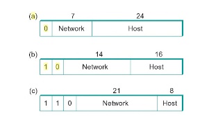
of an IP address is identified in the most significant few bits. If the first
bit is 0, it is a class A address. If the first bit is 1 and the second bit is
0, it is a class B address. If the first two bits are 1 and the third bit is 0,
t is a class C address.
Class A
addresses have 7 bits for network part and 24 bits for host part. So 126 class
A networks each can accommodate 224-2 (about 16 million) hosts. The
0 and 127 are reserved.
Class B
addresses have 14 bits for network part and 16 bits for host part. So 214-2
class B networks each can accommodate 216-2 (about 65,534) hosts.
Class C
addresses have 21 bits for network part and 8 bits for host part. So 221-2
class C networks each can accommodate 28-2 (about 254) hosts. The 0
and 127 are reserved.
There are
approximately 4 billion possible IP addresses, one half for class A, one
quarter for class B and one-eighth for class C address. There are also class D
and class E are there. But class D for multicast and class E are currently
unused.
IP
addresses are written as four decimal integers separated vy dots. Each integer
represents the decimal value contained in 1 byte of the address, starting at
the most significant.
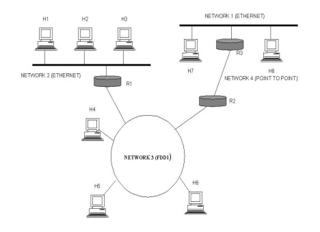
DATAGRAM FORWARDING IN IP
A
datagram is sent from a source to a destination, possibly passing through
several routers along the way. Any node, whether it is a host or a router,
first tries to establish whether it is connected to the same network as the
destination. It compares the network part of the destination address with its
network part. If match occurs, then it directly deliver the packet over the
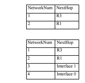
network. Else, then it sends to a router. Among several routers, the nearest
one will be selected. If none of the entries in the table match the destination‟s network number it forwards to
the default router.
Datagram
forwarding algorithm is,
If (networknum of destination = networknum of one
of my interface) then Deliver packet to destination over that interface
Else
If (networknum of destination is in my forwarding
table) then Deliver packet to nexthop router
Else
Deliver
packet to default router
For a
host with only one interface and one default router in its forwarding table,
this simplifies to If (networknum of destination = my networknum ) then
Deliver packet to destination directly Else
Deliver
packet to default router
EXAMPLE
Related Topics