Chapter: Basic Electrical and electronics : Digital Electronics
Counters: Synchronous Counter and Asynchronous Up Down Counter
COUNTERS
•
Counters
are a specific type of sequential circuit.
•
Like
registers, the state, or the flip-flop values themselves, serves as the
“output.”
•
The
output value increases by one on each clock cycle.
•
After the
largest value, the output “wraps around” back to 0.
Benefits of counters
•
Counters
can act as simple clocks to keep track of “time.”
•
You may
need to record how many times something has happened.
–
How many bits have been sent or received?
–
How many steps have been performed in some
computation?
•
All
processors contain a program counter, or PC.
– Programs consist of a list of instructions that
are to be executed one after another
(for the most part).
–
The PC keeps track of the instruction currently
being executed.
– The PC increments once on each clock cycle, and
the next program instruction is then executed.
Counter Types
Asynchronous Counter (Ripple or Serial Counter)
Each FF is triggered one at a time with output
of one FF serving as clock input of next FF in the chain.
Synchronous Counter (a.k.a. Parallel Counter)
All the FF‟ s in the counter are clocked at the same time.
Up Counter
Counter counts from zero to a maximum count.
Down Counter
Counter counts from a maximum count down to
zero.
BCD Counter
Counter counts from 0000 to 1001 before it
recycles.
Pre-settable Counter
Counter that can be preset to any starting
count either synchronously or asynchronously
Ring Counter
Shift register in which the output of the last
FF is connected back to the input of the first FF.
Johnson Counter
Shift
register in which the inverted output of the last FF is connected to the input
of the first FF.
1
Synchronous Counter
There is a problem with the
ripple counter just discussed. The output stages of the flip-flops further down
the line (from the first clocked flip-flop) take time to respond to changes
that occur due to the initial clock signal. This is a result of the internal
propagation delay that occurs within a given flip-flop.
A standard TTL flip-flop may have an internal propagation delay of
30 ns. If you join four flip-flops to create a MOD-16 counter, the accumulative
propagation delay at the highest-order output will be 120 ns. When used in
high-precision synchronous systems, such large delays can lead to timing
problems.
To avoid large delays, you
can create what is called a synchronous counter. Synchronous counters, unlike
ripple (asynchronous) counters, contain flip-flops whose clock inputs are
driven at the same time by a common clock line. This means that output
transitions for each flip-flop will occur at the same time. Now, unlike the
ripple counter, you must use some additional logic circuitry placed between
various flip-flop inputs and outputs to give the desired count waveform.
For example, to create a
4-bit MOD-16 synchronous counter requires adding two additional AND gates, as
shown below. The AND gates act to keep a flip-flop in hold mode (if both input
of the gate are low) or toggle mode (if both inputs of the gate are high). So,
during the 0–1 count, the first flip-flop is in toggle mode (and always is); all
the rest are held in hold mode. When it is time for the 2–4 count, the first
and second flip-flops are placed in toggle mode; the last two are held in hold
mode.
When it is time for the 4–8
count, the first AND gate is enabled, allowing the third flip-flop to toggle.
When it is time for the 8–15 count, the second AND gate is enabled, allowing
the last flip-flop to toggle
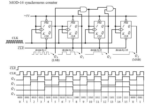
Figure: Mod 16 Synchronous Counters and Cycle
Diagram
The ripple (asynchronous) and synchronous counters discussed so far
are simple but hardly ever used. In practice, if you need a counter, be it
ripple or synchronous, you go out and purchase a counter IC. These ICs are
often MOD-16 or MOD-10 counters and usually come with many additional features.
For example, many ICs allow you to preset the count to a desired number via
parallel input lines.
Synchronous
Up /Down Counter
The down counter counts in
reverse from 1111 to 0000 and then goes to 1111. If we inspect the count cycle,
we find that each flip-flop will complement when the previous flip- flops are
all 0 (this is the opposite of the up counter). The down counter can be
implemented similar to the up counter, except that the AND gate input is taken
from Q’ instead of Q. This is shown in the following Figure of a 4-bit up-down
counter using T flip-flops.
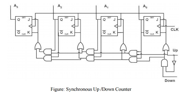
Figure: Synchronous Up /Down Counter
2
Asynchronous Up /Down Counter:
In certain applications, a
counter must be able to count both up and down. The circuit below is a 3-bit
up-down counter. It counts up or down depending on the status of the control
signals UP and DOWN. When the UP input is at 1 and the DOWN input is at 0, the
NAND network between FF0 and FF1 will gate the non-inverted output (Q) of FF0
into the clock input of FF1. Similarly, Q of FF1 will be gated through the
other NAND network into the clock input of FF2. Thus the counter will count up.
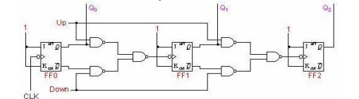
Figure: Asynchronous Up /Down Counter
When the control input UP is at 0 and DOWN is at 1, the inverted
outputs of FF0 and FF1 are gated into the clock inputs of
FF1 and FF2 respectively. If the flip-flops are initially
y reset to 0's, then the counter will go through the following sequence as
input pulses are applied
Notice that an asynchronous
up-down counter is slower than an up counter or a down counter because of the
additional propagation delay introduced by the NAND networks.
Design
of Synchronous Counters
This section begins our study of designing an important class of
clocked sequential logic circuits-synchronous fi ni t e -state machines. Like
all sequential circuits, a finite-state machine determines its outputs and its
next state from its current inputs and current state. A synchronous finite
state machine changes state only on the clocking event.
Related Topics