Chapter: Basic Electrical and electronics : Digital Electronics
Adder
ADDER
1 Half
Adder
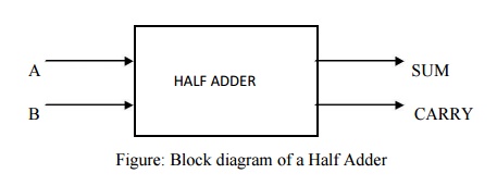
Half
adder is a circuit that will add two bits & produce a sum & a carry
bit. It needs two input bits & two output bits.Fig.4.1 shows the block
diagram of a half adder.
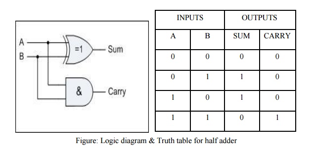
Ex-OR
gate will only produce an output "1" when "EITHER" input is
at logic "1", so we need an additional output to produce a carry
output, "1" when "BOTH" inputs "A" and
"B" are at logic "1" and a standard AND Gate fits the bill
nicely. By combining the Ex-OR gate with the AND gate results in a simple
digital binary adder circuit known commonly as the "Half Adder"
circuit.
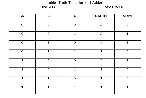
2 Full
Adder
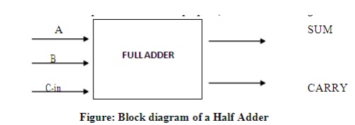
A half
adder has only two inputs &there is no provision to add a carry coming from
the lower order bits when multi addition is performed. For this purpose, a full
adder is designed.
The
1-bit Full Adder circuit is basically two half adders connected together and
consists of three Ex-OR gates, two AND gates and an OR gate, six logic gates in
total. The truth table for the full adder includes an additional column to take
into account the Carry-in input as well as the summed output and carry-output.
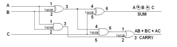
Figure: Logic diagram of a Full adder using two
Half Adders
Table:
Truth Table for Full Adder
Related Topics