Chapter: Microprocessor and Microcontroller
8085 Interrupts
8085 INTERRUPTS
Interrupt Structure:
Interrupt is the
mechanism by which the processor is made to transfer control from its current
program execution to another program having higher priority. The interrupt
signal may be given to the processor by any external peripheral device.
The program or the
routine that is executed upon interrupt is called interrupt service routine
(ISR). After execution of ISR, the processor must return to the interrupted
program. Key features in the interrupt structure of any microprocessor are as
follows:
i. Number and types of interrupt signals
available.
ii. The address of the memory where the ISR is
located for a particular interrupt signal. This address is called interrupt
vector address (IVA).
iii. Masking and unmasking feature of the interrupt
signals.
iv. Priority among the interrupts.
v. Timing of the interrupt signals.
vi. Handling and storing of information about the
interrupt program (status information).
Types of Interrupts:
Interrupts are classified based on their
maskability, IVA and source. They are classified as:
i. Vectored and Non-Vectored Interrupts
· Vectored interrupts require the IVA to be
supplied by the external device that gives the interrupt signal. This technique
is vectoring, is implemented in number of ways.
· Non-vectored interrupts have fixed IVA for
ISRs of different interrupt signals.
ii. Maskable and Non-Maskable Interrupts
· Maskable interrupts are interrupts that can be
blocked. Masking can be done by software or hardware means.
· Non-maskable interrupts are interrupts that
are always recognized; the corresponding ISRs are executed.
iii. Software and Hardware Interrupts
· Software interrupts are special instructions,
after execution transfer the control to predefined ISR.
· Hardware interrupts are signals given to the
processor, for recognition as an interrupt and execution of the corresponding
ISR.
Interrupt Handling
Procedure:
The following sequence
of operations takes place when an interrupt signal is recognized:
i. Save the PC content and information about
current state (flags, registers etc) in the stack.
ii. Load PC with the beginning address of an ISR
and start to execute it.
iii. Finish ISR when the return instruction is
executed.
iv. Return to the point in the interrupted program
where execution was interrupted.
Interrupt Sources and
Vector Addresses in 8085:
Software Interrupts:
8085 instruction set
includes eight software interrupt instructions called Restart (RST)
instructions. These are one byte instructions that make the processor execute a
subroutine at predefined locations. Instructions and their vector addresses are
given in Table 6.
Table 6 Software interrupts and their vector
addresses
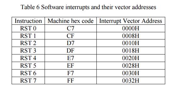
The software
interrupts can be treated as CALL instructions with default call locations. The
concept of priority does not apply to software interrupts as they are inserted
into the program as instructions by the programmer and executed by the
processor when the respective program lines are read.
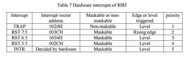
Hardware Interrupts
and Priorities:
8085 have five
hardware interrupts – INTR, RST 5.5, RST 6.5, RST 7.5 and TRAP. Their IVA and
priorities are given in Table 7.
Table 7 Hardware interrupts of 8085
Masking of Interrupts:
Masking can be done for four hardware
interrupts INTR, RST 5.5, RST 6.5, and RST 7.5. The masking of 8085 interrupts
is done at different levels. Fig. 13 shows the organization of hardware
interrupts in the 8085.
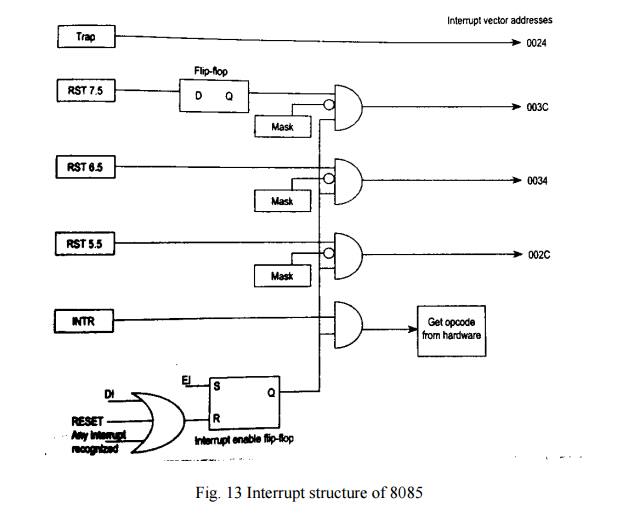
The Fig. 13 is
explained by the following five points:
i. The maskable interrupts are by default masked
by the Reset signal. So no interrupt is recognized by the hardware reset.
ii. The interrupts can be enabled by the EI instruction.
iii. The three RST interrupts can be selectively
masked by loading the appropriate word in the accumulator and executing SIM
instruction. This is called software masking.
iv. All maskable interrupts are disabled whenever
an interrupt is recognized.
v. All maskable interrupts can be disabled by
executing the DI instruction.
RST 7.5 alone has a
flip-flop to recognize edge transition. The DI instruction reset interrupt
enable flip-flop in the processor and the interrupts are disabled. To enable
interrupts, EI instruction has to be executed.
SIM Instruction:
The SIM instruction is used to mask or unmask
RST hardware interrupts. When executed, the SIM instruction reads the content
of accumulator and accordingly mask or unmask the interrupts. The format of
control word to be stored in the accumulator before executing SIM instruction
is as shown in Fig. 14.
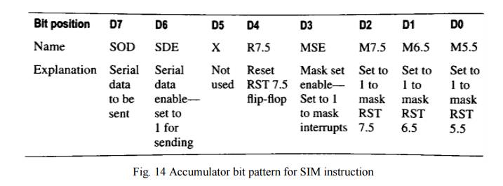
In addition to masking
interrupts, SIM instruction can be used to send serial data on the SOD line of
the processor. The data to be send is placed in the MSB bit of the accumulator
and the serial data output is enabled by making D6 bit to 1.
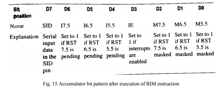
RIM Instruction:
RIM instruction is
used to read the status of the interrupt mask bits. When RIM instruction is
executed, the accumulator is loaded with the current status of the interrupt
masks and the pending interrupts. The format and the meaning of the data stored
in the accumulator after execution of RIM instruction is shown in Fig. 15.
In addition RIM instruction is also used to
read the serial data on the SID pin of the processor. The data on the SID pin
is stored in the MSB of the accumulator after the execution of the RIM
instruction.
Ex: Write an assembly
language program to enables all the interrupts in 8085 after reset.
EI
: Enable interrupts
MVI A,
08H : Unmask the interrupts
SIM
: Set the mask and unmask using SIM instruction
Timing of Interrupts:
The interrupts are
sensed by the processor one cycle before the end of execution of each
instruction. An interrupts signal must be applied long enough for it to be
recognized. The longest instruction of the 8085 takes 18 clock periods. So, the
interrupt signal must be applied for at least 17.5 clock periods. This decides
the minimum pulse width for the interrupt signal.
The maximum pulse width for the interrupt
signal is decided by the condition that the interrupt signal must not be
recognized once again. This is under the control of the programmer.
Related Topics