Chapter: Physics : Quantum Physics
Quantum Physics
QUANTUM PHYSICS
OBJECTIVES
1) To explain the principle of black body radiation
2) To reveal the energy distribution in black body radiation
3) To derive Planck’s equation for radiation
4) To explain the particle and wave nature (matter waves) of the quantum particles.
5) To derive de-Broglie equation related with momentum and wavelength of the particle
6) To discuss the properties of the matter waves and explain the experimental evidence of matter waves.
7) To derive the Schrödinger wave equation for the motion of quantum particles.
8) To discuss the importance of uncertainty principle
9) To derive application of Schrödinger equation for a particle in one – dimensional box and its importance.
10) To study the principle, mechanism, and applications of optical based instruments
11) To explore the method to find the attitude of sun and height of a tower building
12) To understand the operating principle and applications of optical microscope ,TEM and SEM
13) To understand the role of optical instruments in material characterization.
Laws of thermodynamics and classical laws of electricity and magnetism provide the basis for explanation of all phenomena in classical physics. It was general belief of the scientists that these laws would suffice to account for any subsequent discovered phenomena. Classical mechanics successfully explained the motion of the objects, which are directly observable. When the objects are not observable, then the concept of classical mechanics cannot be applied.
The phenomena in the realm of the atoms, nuclei and elementary particles are commonly reefed to as quantum phenomena and subject matter containing all these phenomena constitutes what is known as Quantum Physics.
1 Inadequacy of Classical Mechanics
According to the classical mechanics, if we consider the case of an electron moving round the nucleus, its energy should decrease (because the accelerated charged particle loses energy in the form of electromagnetic waves) and therefore its velocity should decrease continuously. The ultimate result is that the electron comes closer and closer to the nucleus until it collapses. This shows the instability of the atom; it is in contradiction to the observed fact of the stability of an atom. Thus the classical mechanics fails to explain the stability of an atom.
The classical mechanics also failed to explain the spectrum of the hydrogen atom. Acc to the classical theory, the excited atoms of hydrogen emit electromagnetic radiations of all wavelengths continuously, while it is observed that they emit the radiation of certain wavelengths only.
2Difficulties with classical theories of Black Body Radiation and Origin of Quantum Theory of Radiation
We know that when bodies radiate energy, their temperature falls until the loss of energy is compensated by an external source. In case of heat radiation, we can obtain the thermal equilibrium by maintaining the body at a fixed temperature with the help of some heat-giving source. In this case he body gives as much radiation as it receives. If the body absorbs all the incident radiation, then it is called Black Body radiation. In actual practice, it is not possible to realize a perfectly black body, but an enclosure provided with a small opening serves the purpose because the radiation entering the enclosure will be reflected many times inside the enclosure and ultimately absorbed.
3 BLACK BODY RADIATION:
Perfect black body:
A perfect black body is one which absorbs and emits in all the radiations (corresponding to all wavelengths) that fall on it. The radiation given out by a perfect black body is called Black body radiation.
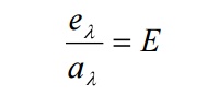
Kirchhoff’s law:
Ratio of emissive power to the coefficient of absorption of any given wavelength is the same for all bodies at a given temperature and is equal to the emissive power of the black body at that temperature.
Experiment:
In practice a perfect black body is not available. Therefore let us consider a hollow sphere coated with lamp black on its inner surface.
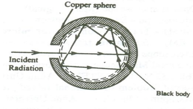
A fine hole is made for radiations to enter into the sphere as shown in the figure.
Now when the radiations are made to pass through the hole it undergoes multiple reflections and are completely absorbed. Thus the black body acts as a perfect absorber.
Now when the black body is placed in a temperature bath of fixed temperature, the heat radiations will come out only through the hole in the sphere and not through the walls of the sphere.
Therefore, we can conclude that the radiations are emitted from the inner surface of the sphere and not from the outer surface of the sphere. Thus a perfect black body is a perfect absorber and also a perfect radiator of all wavelengths.
Energy spectrum:
When a perfect black body is allowed to emit radiations at different temperatures , then the distribution of the energy for different wavelengths at various temperatures is obtained as shown in the figure.
From figure the following results are formulated.
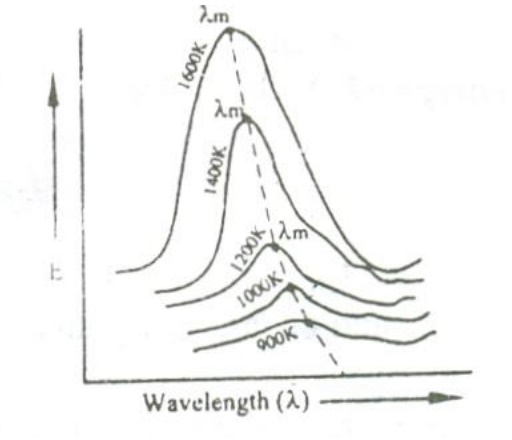
i. The energy distribution is not uniform for a given temperature.
ii. The intensity of radiation (E) increases with respect to the increase in wavelength at at particular wavelength in becomes maximum (λm) and after this it starts decreasing with respect to the increase in wavelength.
iii. When the temperature is increased, the maximum wavelength (λm) decreases.
iv. For all the wavelengths an increase in its temperature causes increase in energy.
iv. The total energy emitted at any particular temperature can be calculated from the area under that particular curve.
Laws for explaining the energy distribution:
1. Stefan- Boltzmann Law
According to this law the radiant energy (E) of the body is directly proportional to the fourth power of the temperature (T) of the body.

2. Wien’s displacement law:
This law states that the product of then wavelength λ maximum energy and the absolute temperature (T) is a constant.
λ mT Cons tan t
This law shows that, as the temperature increases, the wavelength corresponding to maximum energy decreases.
Wien also showed that the maximum energy (Emax) is directly proportional to the fifth power of the absolute temperature.
Em ax Dir Pro T 5
Em ax = Cons tan tT 5
By deducing this law he obtained a law called Wien’s law of distribution of energy (Eλ), given by
3. Raleigh Jeans law:
According to this law, the energy distribution is directly proportional to the absolute temperature and is inversely proportional to the fourth power of the wavelength.
It is governed by the equation

Where KB is Boltzmann Constant.
This law holds well only for longer wavelength regions and not for shorter wavelengths.
It is found that, both Wien’s and Raleigh Jeans law don’t agree with the experimental results. Therefore we can conclude that the classical theory was not able to explain the emission of black body radiation. Thus Max Planck used Quantum theory to explain Black body radiation.
4 PLANCK’S HYPOTHESIS
Planck suggested that the correct results could be obtained if the energy of oscillating electrons is taken as discrete rather than continuous. He suggested quantum theory of radiation. Planck suggested in deriving the formula, which agrees extremely well with experimental results. He derived the radiation law by using the following assumptions.
a. A black body chamber is filled up not only with radiation, but also with simple harmonic oscillators or harmonic oscillators or resonators of molecular dimensions. They can vibrate with all possible frequencies.
b. The frequency of radiation emitted by an oscillator is the same as the frequency of its vibration.
c. An oscillator cannot emit energy in a continuous manner. It can emit energy in the multiples of a small unit called Quantum (Photon).
If an oscillator is vibrating with a frequency γ , it can radiate in quantas of magnitude hγ . The oscillator can have only discrete energy En given by
En = n hγ = nɛ where hγ = ɛ
The emission of radiation corresponds to a decrease and absorption to an increase in the energy and amplitude of an oscillator.
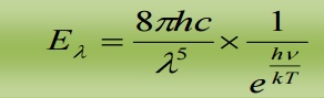
4.1 Planck’s law of radiation:
Statement:
The energy density of heat radiation emitted from an enclosure at temperature T in the wavelength range from λ to λ + λd is given by
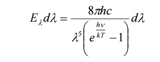
Here h = Planck’s constant
C= speed of the light
K= Boltzmann constant
T = temperature of the enclosure
4.2 DERIVATION OF PLANCK’S LAW OF RADIATION
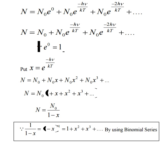
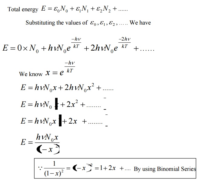
Assume that a black body consists of energy by a large number of atomic oscillators.
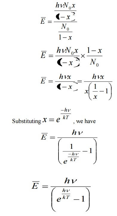
Average energy BarE = E/N
Where E is the total energy and N is the number of oscillators.
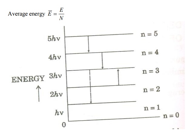
Number of atomic oscillators in ground state = N 0
From Maxwell’s distribution law, the number of oscillators having energy ɛ n in excess of ground state energy (ɛ 0 ) is given by
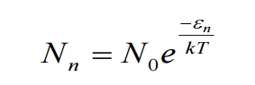
Where T – Absolute temperature
K – Boltzmann’s Constant
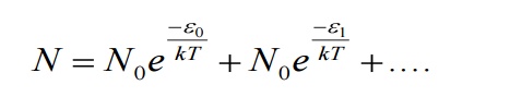
Let N be the total number of Planck’s oscillators and N1, N2, N3 etc be the number of oscillators with energies ɛ0 , ɛ1 , ɛ2 .......... , then
We know from Planck’s quantum theory, ɛ can be a quanta of integral values of hγ and so the possible values of ɛ are 0, 2hγ, and 3hγ etc.
Number of oscillators per unit volume in the wavelength range λ and λ+dλ is given by
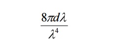
The energy density of radiation between wavelengths λ and λ+dλ is given by
Eλdλ = (Number of oscillators per unit volume in the interval λ and λ+dλ) x (Average energy per oscillator)
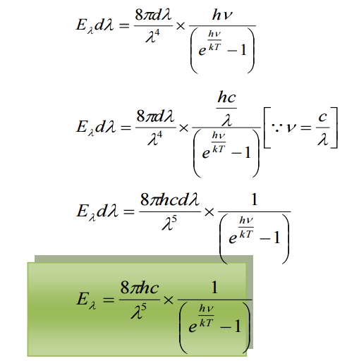
This equation represents Planck’s radiation law in terms of wavelength.
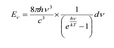
This law explained significantly the entire blackbody spectrum. It can also be expressed in terms of frequencies by substituting
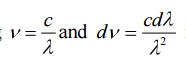
in the Planck law. Then
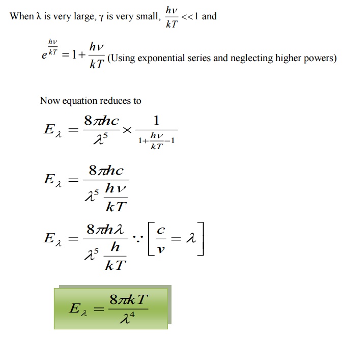
4.2.1 DEDUCTION OF WIEN’S DISPLACEMENT LAW:
When λ is small, γ is very large, hence 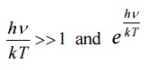 is large when compared to 1. Hence, ‘1’ is neglected in the denominator
Hence the equation reduces to
This is Wien’s displacement law.
Therefore Planck’s law reduces to Wien’s displacement for smaller wavelengths.
4.2.2 DEDUCTION OF RAYELIGH JEANS LAW:
This is Rayleigh – Jeans law.
Therefore, Planck’s law reduces to Rayleigh – Jeans law for longer
wavelength.
Planck’s formula is found to agree remarkably well with experimental observations of Lummer, Pringsheim, Kurlbaum etc. and is thus an established formula for all validity of quantum hypothesis.
5 COMPTON EFFECT:
When a beam of monochromatic radiation such as x- rays, gamma rays etc of high frequency is allowed to fall on the scatterer, the beam is scattered into two components
i. One component having the same frequency or wavelength as that of the incident photon, so called unmodified radiation
ii. The other component having lower frequency or higher wavelength
compared to incident radiation , so called modified radiation
This effect is called Compton Effect.
5.1 Compton shift:
When a photon of energy ‘hγ’ collides with an electron of a scatterer at rest; the photon gives its energy to the electron. Therefore the scattered photon will have lesser energy or lower frequency or higher wavelength compared to the wavelength of incident photon. Since the electron gains energy, it recoils with velocity’s’. This effect is called Compton Effect and the shift in wavelength is called Compton shift.
Thus as a result of Compton scattering, we get (i) unmodified radiations (ii) modified radiations and (iii) a recoil electron.
5.2 THEORY OF COMPTON EFFECT:
Principle:
In Compton scattering the collision between a photon and an electron is considered. Then by applying the laws if conservation of energy and momentum, the expression for Compton wavelength is derived.
Assumptions:
1. The collision occurs between the photon and an electron in the scattering material
2. The electron is free and is at rest before collision with the incident photon.
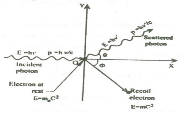
With these assumptions, let us consider a photon energy hγ colliding within electron at rest.
During the collision process, a part of kinetic energy is given to the electron, which in turn increases the kinetic energy of the electron and hence it recoils at an angle of φ as shown.
![]() The scattered photon moves with an energy h
The scattered photon moves with an energy h![]() ( lesser than hγ) , at an angle θ with respect to the original direction.
( lesser than hγ) , at an angle θ with respect to the original direction.
Let us find the energy and momentum components before and after collision.
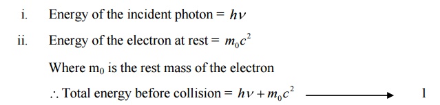
ENERGY BEFORE COLLISION.
ENERGY AFTER COLLISION:
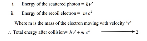
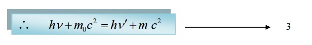
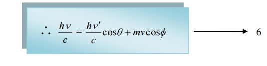
We know according to law of conservation of energy
Total energy before collision = Total energy after collision
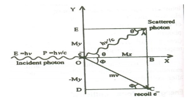
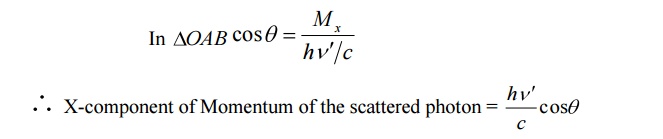
X-component of Momentum before collision:
i. X-component momentum of the incident photon = ɦv/c
ii. X-component momentum of the electron at rest = 0
Total X-component of Momentum before collision = ɦv/c ----- (3)
X-component of Momentum after collision:
i. X-component of the scattered photon can be calculated from the figure.
ii X-component Momentum of recoil electron an be calculated as follows
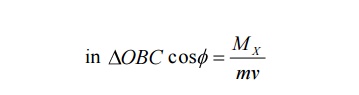
X-component Momentum of recoil electron = mv cos ϕ
Total X-component of Momentum after collision
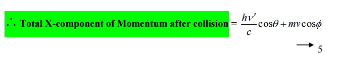
We know according to the law of conservation of momentum
Total Momentum before collision = Total Momentum after collision
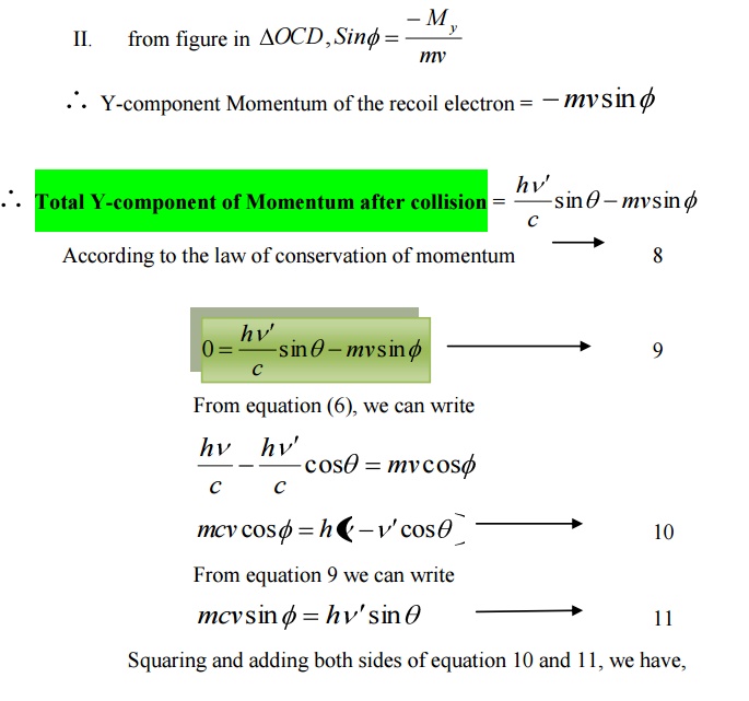
Y-component of Momentum before collision
I. Y – component momentum of the incident photon = 0 II. Y – component of the electron at rest = 0
Total Y _component of momentum before collision = 0 - --- >> 7
Y-component of Momentum after collision
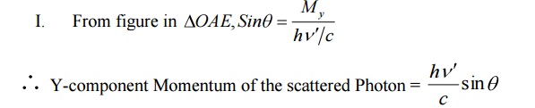
= Y-component Momentum of the scattered Photon
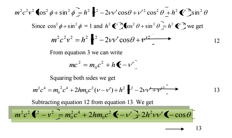
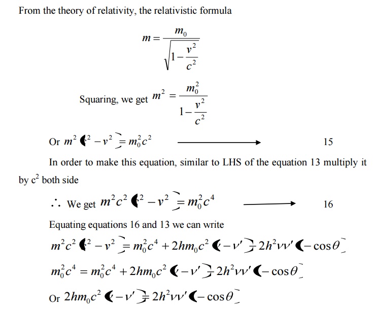
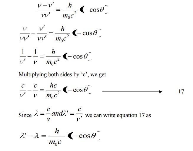
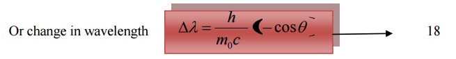
Equation 18 represents the shift in wavelength, i.e., Compton shift which is independent of the incident radiation as well as the nature of the scattering substance.
Thus the shift in wavelength or Compton shift purely depends upon the angle of scattering.
5.3 SPECIAL CASES:
Case (i) when θ = 0 cosθ = 1

This implies that at θ = 0, the scattering is absent and the out coming radiation has the same wavelength or frequency as that of the incident radiation. Thus we get the output as a single peak.
Case (ii) when θ = 900 ;cosθ = 0

Substituting the values of h, m0, and c we have
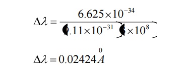
This wavelength is called Compton Wavelength, which has good agreement with the experimental results.
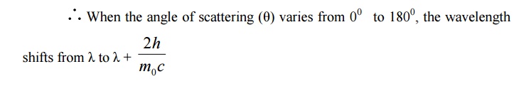
Case (iii) when θ = 1800 ;cosθ = 0
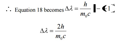
Substituting the values of h, m0, and c we have
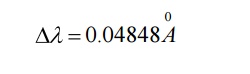
Thus for θ =1800 the shift in wavelength is found to be maximum
5.4 EXPERIMENTAL VERIFICATION OF COMPTON EFFECT
Principle:
When a photon of energy hγ collides with a scattering element, the scattered beam has two components, viz., one of the same frequencies or wavelength as that of the incident radiation and the other has lower frequency or higher wavelength compared to incident frequency or wavelength. This effect is called Compton Effect and the shift in wavelength is called Compton Shift.
Construction:
It consists of an X-ray tube fro producing X-rays. A small block of Carbon C (scattering element) is mounted on a circular table as shown in the figure.
A Bragg’s spectrometer (Bs) is allowed to freely swing in an arc about the scattering element to catch the scattered photons. Slits S1and S2 helps to focus the X-rays onto the scattering element.
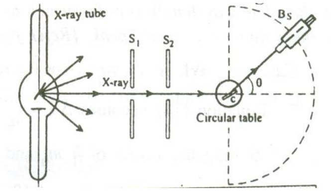
Working:
X-rays of monochromatic wavelength ’λ’ is produced from an X-ray tube and is made to pass through the slits S1 and S2. These X- rays are made to fall on the scattering element. The scattered X-rays are received with the help of the Bragg’s spectrometer and the scattered wavelength is measured.
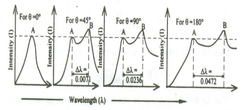
The experiment is repeated for various scattering angles and the scattered wavelengths are measured. The experimental results are plotted as shown in the figure.
In this figure when the scattering angle θ = 00, the scattered radiation peak will be the same as that of the incident radiation Peak ‘A’. now , when the scattering angle is increased, for one incident radiation peak A of wavelength ‘λ’ we get two scattered peaks ‘A’ and B. here the peak A is found to be of same wavelength as that of the incident wavelength and the peak ‘B’ is of greater wavelength than the incident radiation
The shift in wavelength or difference in wavelength ∆λ of the two scattered beams is found to increase with respect to the increase in the scattering angle.
At θ = 900, the ∆ is found to be 0.0236 0.02424, which has good agreement with the theoretical results. Hence this wavelength is called Compton wavelength and the shift in wavelength is called Compton shift.
6 DUAL NATURE OF RADIATION (LIGHT) AND MATTER (PARTICLES) – MATTER
WAVES
de- Broglie concept of dual nature:
The universe is made of radiation (light) and matter (particles). The light exhibits the dual nature (ie.) it can behave both a wave (interference, diffraction, phenomenon) and as a particle (Compton Effect, photo electric effect etc.)
Since the nature loves symmetry, in 1923 Louis debroglie suggested that an electron or any other material particle must exhibit wave like properties in addition to
particle nature.
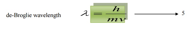
The waves associated with a material particle are called as matter waves. De-Broglie wavelength:
From the theory of light, considering a photon as a particle the total energy of the photon is given by
Where m is the mass of the particle
c is the velocity of light
Considering the photon as a wave, the total energy is given by
E = hγ ------------- > (2)
Where h is the Planck’s constant
Γ is the frequency of the radiation.
From equations (1) and (2)
E = mc2 = hγ --------- ((3))
We know Momentum = Mass × velocity
p = mc
hv=pc
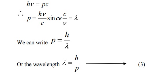
de-Broglie suggested that the equation 3 can be applied both for photons and material particles. If m is the mass of the particle and v is the velocity the particle, then
Momentum p = mv
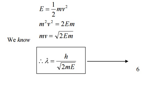
6.1 de-Broglie wavelength in terms of energy
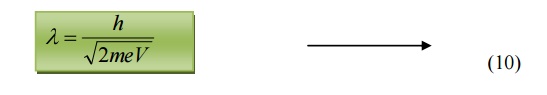
6.2 de-Broglie wavelength in terms of Voltage
If a charged particle of charge ’e’ is accelerated through a potential difference
Then the Kinetic Energy of the particle = ½ mv2 --à (7)
Also we know energy = eV -------- (8)
Equating 7 and 8, we get,

Multiplying by ‘m’ both sides, we get
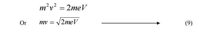
Substituting 9 in 5, we get
de-Broglie wavelength
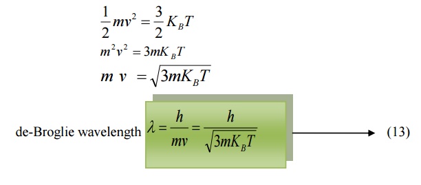
6.3 de-Broglie wavelength in terms of Temperature
When a particle like neutron is in thermal equilibrium at temperature T, then they possess Maxwell distribution of velocities.
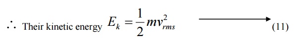
Where vrm s is the Root mean square velocity of the particle.
Also, we know energy = 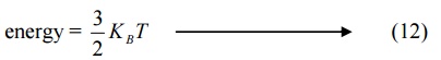
Where KB is the Boltzmann constant.
Equating (11) and (12) we get
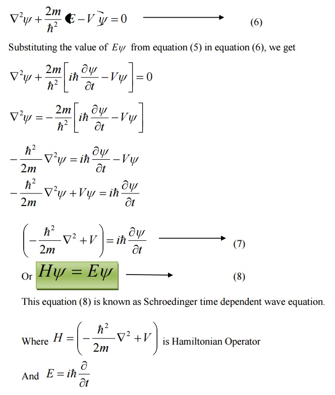
7 SCHROEDINGER WAVE EQUATION
Schröedinger wave equation describes the wave nature of a particle in the mathematical form. It is the basic equation of motion of matter waves.
If the particle has wave properties, then there should be some sort of wave equation to describe the behavior of that particle.
Schrödinger connected the expression of de-Broglie’s wavelength with the classical wave equation for a moving particle and he obtained a new wave equation.
7.3FORMS OF SCHROEDINGER WAVE EQUATION
There are two forms of Schröedinger wave equation. They are
a. Time independent wave equation
b. Time dependent wave equation
8 SCHROEDINGER TIME INDEPENDENT WAVE EQUATION
Consider a system of stationary waves associated with a particle.
Let x, y, z be the coordinates of the particle and ψ be the wave displacement for de-Broglie’s waves at any time t.
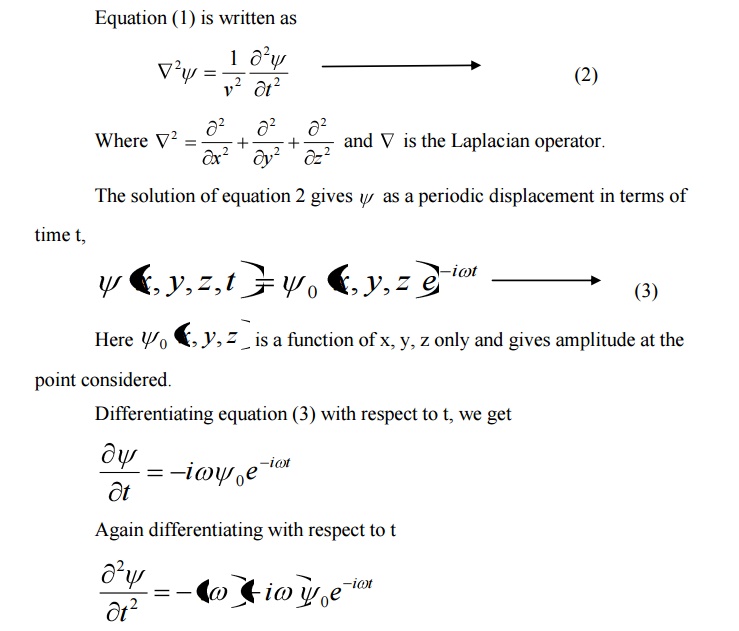
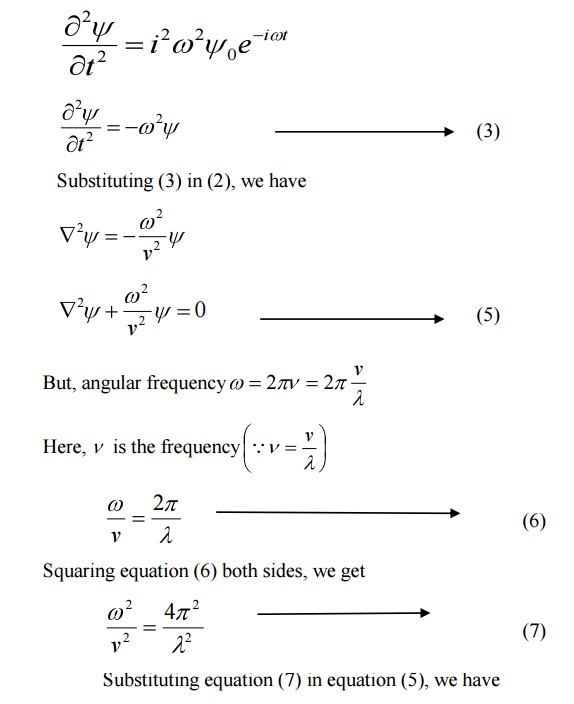
The classical differential equation of a wave motion is given by
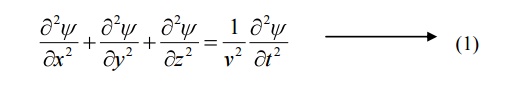
Here v is the wave velocity Equation (1) is written as
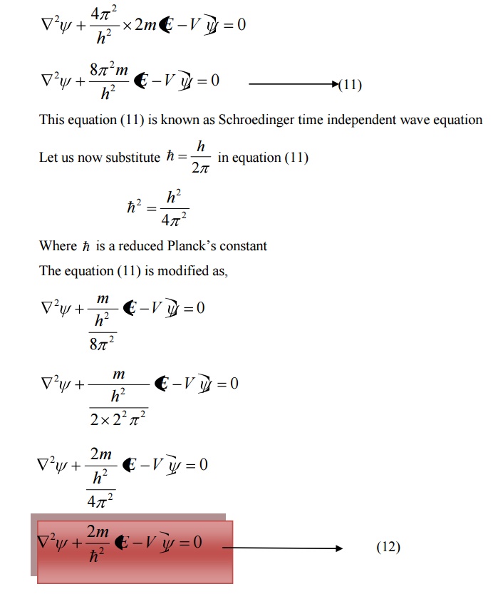
9 SCHROEDINGER TIME DEPENDENT WAVE EQUATION
Schoredinger time independent wave equation is derived from Schroedinger time independent wave equation.
The solution of classical differential equation of the wave motion is given by
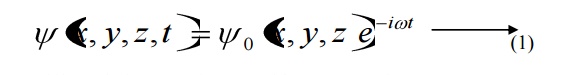
Differentiating equation (1) with respect to time t we get
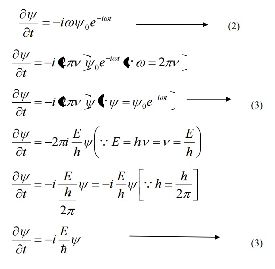
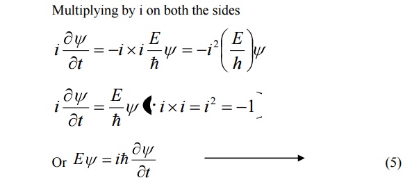
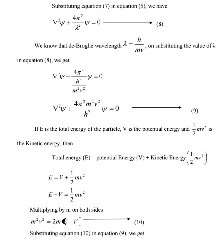
We know that Schroedinger time independent wave equation is given by
10 PHYSICAL SIGNIFICANCE OF WAVE FUNCTION (ψ)
1.The variable quantity that characterizes d-Broglie wave is called wave function .
2.The wave function represents the variations in the matter waves and it connects the particle nature and its associated wave nature statistically.
3.The wave function associated with a moving particle at a particular instant of time and at a particular point in space is related to the probability of finding the particle at that instant and at that point.
4. The probability 0 corresponds to the certainty of not finding the particle and probability 1 corresponds to the certainty of finding the particle.
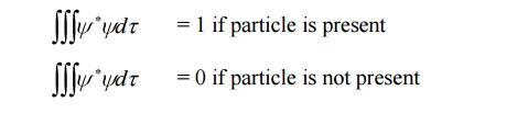
5.The wave function is a complex quantity that cannot be measured.
6.The probability of finding a particle at particular region must be real and positive, but the wave function ψ is in general a complex quantity.
The probability density is given by

11 PARTICLE IN A ONE DIMENSIONAL BOX
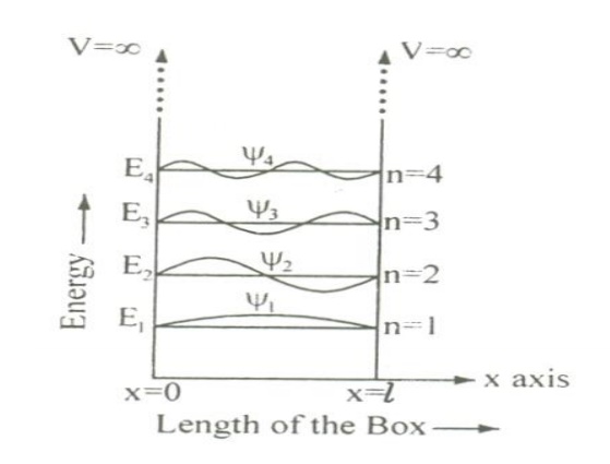
Let us consider particle (electron) of mass ’m’ moving along the x-axis, enclosed in a one dimensional potential box as shown in the figure.
Since the walls are of infinite potential the particle does not penetrate out from the box.
Also, the particle is confined between the length ‘l’ of the box and has elastic collisions with the walls. Therefore, the potential energy of the electron inside the box is constant and can be taken as zero for simplicity.
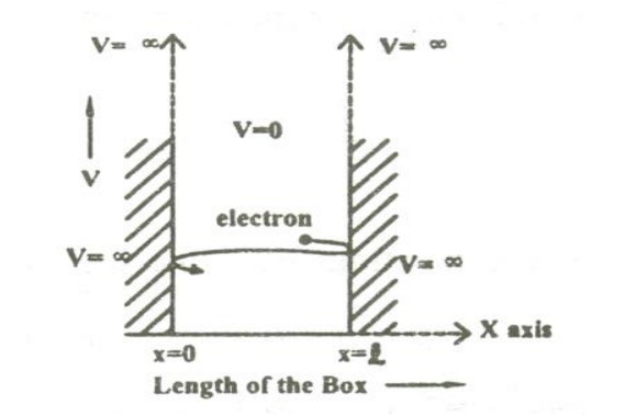
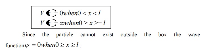
We can say that the Outside the box and on the wall of the box, the potential energy V of the electron is .
Inside the box the potential energy (V) of the electron is zero.
In other words we can write the boundary condition as
To find the wave function of the particle within the box of length ‘l’, let us consider the Schroedinger one dimensional time independent wave equation(i.e.,)
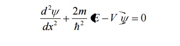
Since the potential energy inside the box is zero [i.e. =0], the particle has kinetic energy alone and thus it is named as a free particle or free electron
For a free particle (electron), the Schroedinger wave equation is given by
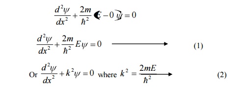
Equation (1) is a second order differential equation; therefore, it should have solution with two arbitrary constants.
The solution for equation (1) is given by
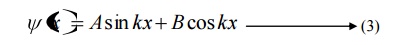
Where A and b are called Arbitrary constants, which can be found by applying the boundary conditions.
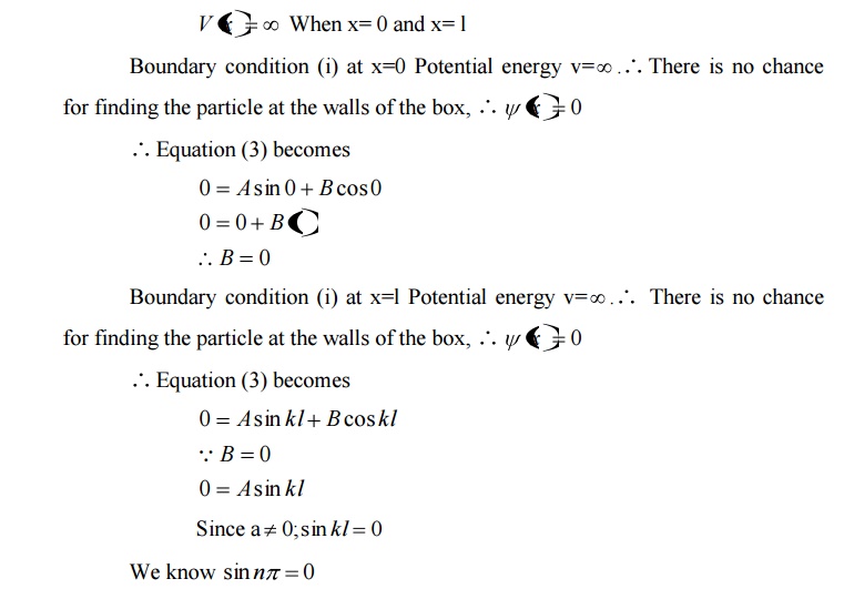
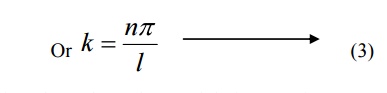
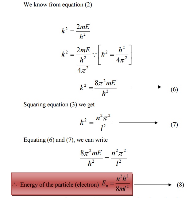
Comparing two equations, we can write kl=nπ where n is an integer.
Substituting the value of B and k in equation 3 we can write the wave function associated with the free electron confined in a one dimensional box as

Energy of the particle(Electron)
From equations (8) and (5) we can say that, for each value of ‘n’, there is an energy level and the corresponding wave function.
Thus we can say that, each value of En is known as Eigen value and the corresponding value of ψn is called Eigen function.
Energy levels of an electron
For various values of ‘n’ we get various energy values of the electron. The lowest energy value or ground state energy value can be got by substituting n = 1 in equation (8)
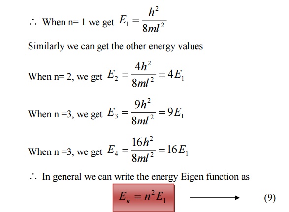
It is found that from the energy levels E1,E2,E3 etc the energy levels of an electron are discrete.
This is the great success which is achieved in Quantum Mechanics than classical mechanics, in which the energy levels are found to be continuous.
The various energy Eigen values and their corresponding Eigen functions of an electron enclosed in a one dimensional box is as shown in the figure. Thus we have discrete energy values.
Normalization of the wave function
Normalization:
It is the process by which the probability (P) of finding the particle (electron) inside the box can be done.
We know that the total probability (P) is equal to 1 means then there is a particle inside the box.
For a one dimensional potential box of length ’l’ the probability
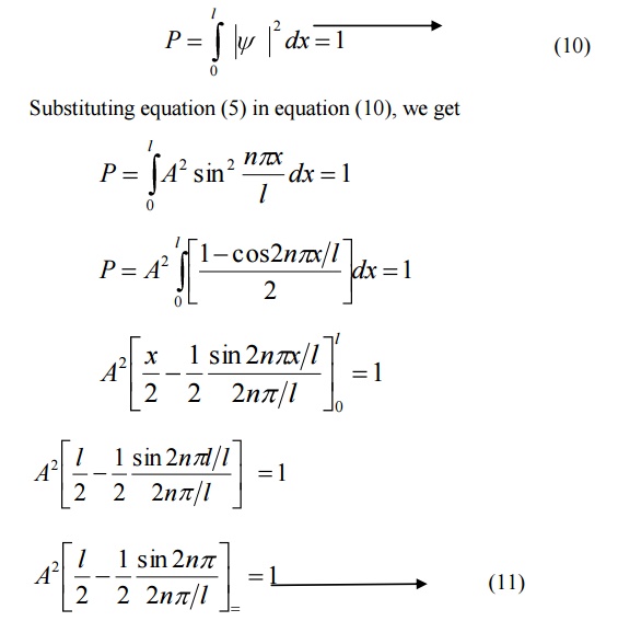
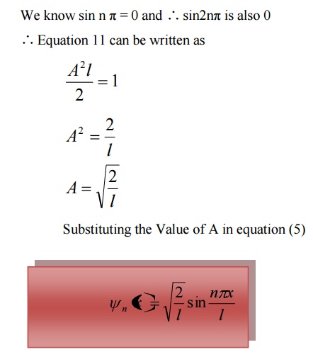
The normalized wave function and their energy values are as shown in the figure.
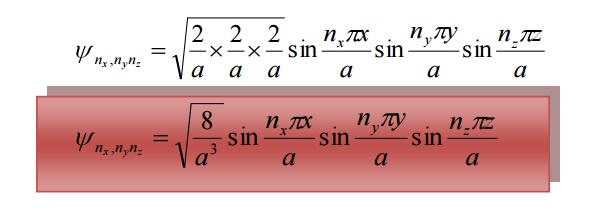
The solution of one-dimensional potential box can be extended for a three dimensional potential box. In a three dimensional potential box, the particle (electron) can move in any direction in space. Therefore instead of one quantum number ‘n’ , we have to use three quantum number nx,ny, nz corresponding to the three coordinate axis x,y,z respectively
The energy of the particle = Ex + Ey+ Ez
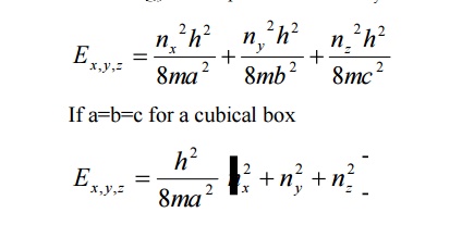
The corresponding normalized wave function of an electron in a cubical box can be written as
12 DEGENERACY AND NON-DEGENERACY
Degeneracy:
It is seen from equation (3) and equation (3), for several combination of quantum numbers we have same energy Eigen value but different Eigen functions. Such states and energy levels are called Degenerate state.
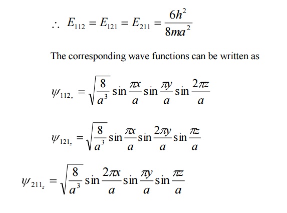
The three combinations of quantum numbers (112), (121) and (211) which gives same Eigen value but different Eigen functions are 3 fold degenerate state.
Example: nx =1 , ny =1 , nz =2
Then nx2+ny2+nz2 6
Similarly for the other two combinations also it is 6 only.
Non –degeneracy:
For various combinations of quantum number if we have same energy value and same (one) Eigen function then such states and energy levels are called Non – degenerate state.
ELECTRON MICROSCOPE
It is a type of microscope in which instead of light beam, a beam of electrons are used to form a large image of very small object. These microscopes are widely used in the field of engineering and medicine.
Principle:
A stream of electrons is passed through the object and the electron which carries the information about the object are focused by electric and magnetic fields.
Since the resolving power is inversely proportional to the wavelength, the electron microscope has high resolving power because of its shorter wavelength.
Construction:
An electron microscope is similar to that of an optical microscope. Here the focusing of electrons can be done either by magnetic lens or by electrostatic lens. Normally in electron microscope magnetic lenses are used for focusing.
In general, the magnetic lenses are made of two coils C1 and C2 enclosed inside the iron cases which have one hole as shown.
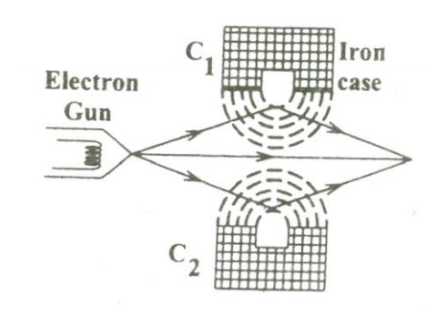
When the holes face each other, the magnetic field in space between the two coils focuses the electrons emerging out from the electron gun. Similarly the divergence of the electrons can also be made by adjusting the position of the holes in the iron cases.
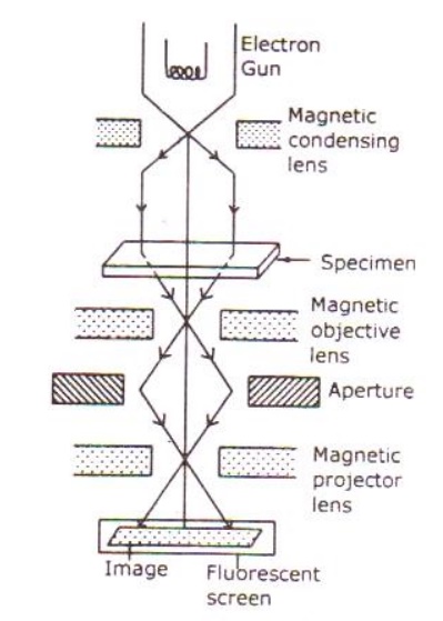
The essential parts of an electron microscope are as shown in the figure and for comparison an optical microscope is also shown aside.
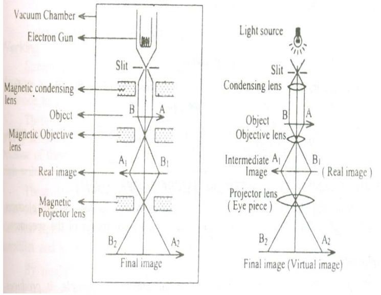
The electron microscope consists of an electron gun to produce the stream of electrons. Similar to the condensing lens, objective and eye piece in an optical microscope here three magnetic lenses are used.
a. Magnetic condensing lens
b. Magnetic objective lens
c. Magnetic projector lens
The whole arrangement is kept inside a vacuum chamber to allow the passage of electron beam.
Working:
Stream of electrons are produced and accelerated by the electron gun. The electron beam is made to pass through the center of the doughnut shaped magnetic condensing lens. These electrons are made as parallel beam and are focused on to the object.
The electrons are transmitted more in the less dense region of the object and is transmitted less (i.e.,) absorbed by the denser region of the object.
Thus the transmitted electron beam on the falling over the magnetic objective lens, resolves the structure of the object to form a magnified real image of the object. Further the image can be magnified by the magnetic projector lens and the final image is obtained on the fluorescent screen.
In order to make a permanent record of the image of the object, the final image can also be obtained on a photographic plate.
Advantages:
a. It can produce magnification as high as 1, 00,000 times as that of the size of the object.
b. The focal length of the microscopic system can be varied.
Disadvantages:
It has a very wide area of applications (e.g) in biology, metallurgy, physics,
chemistry, medicine, engineering etc.
a. It is used to determine the complicated structure of the crystals.
b. It is used in the study of the colloids.
c. In industries it is used to study the structure of textile fibers, surface of metals, composition of paper, paints etc.
d. In the medical field it is used to study about the structure of virus, bacterial etc which are of smaller size.
SCANNING ELECTRON MICROSCOPE
Scanning electron microscope is an improved model of an electron microscope. SEM is used to study the three dimensional image of the specimen.
Principle:
When the accelerated primary electrons strikes the sample , it produces secondary electrons . these secondary electrons are collected by a positive charged electron detector which in turn gives a 3- dimensional image of the sample.
Construction:
It consists of an electron gun to produce high energy electron beam. A magnetic condensing lens is used to condense the electron beam and a scanning coil is arranged in-between magnetic condensing lens and the sample.
The electron detector (Scintillator) is used to collect the secondary electrons and can be converted into electrical signal. These signals can be fed into CRO through video amplifier as shown.
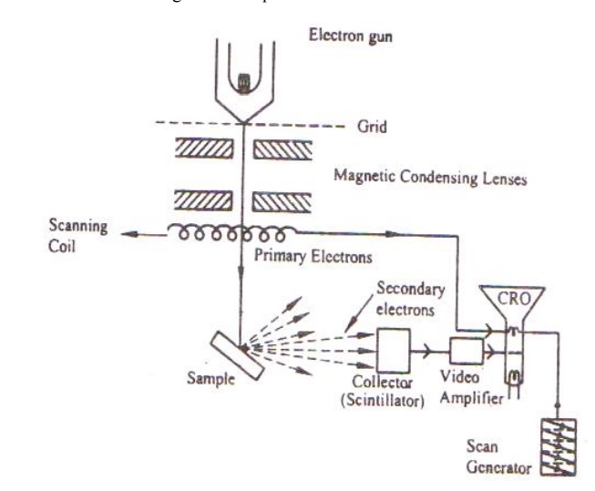
Working:
Stream of electrons are produced by the electron gun and these primary electrons are accelerated by the grid and anode. These accelerated primary electrons are made to be incident on the sample through condensing lenses and scanning coil.
These high speed primary electrons on falling over the sample produces low energy secondary electrons. The collection of secondary electrons are very difficult and hence a high voltage is applied to the collector.
These collected electrons produce scintillations on to the photo multiplier tube are converted into electrical signals. These signals are amplified by the video amplifier and is fed to the CRO.
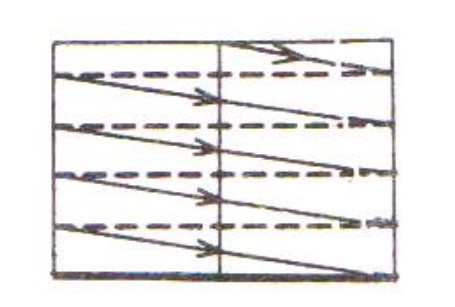
By similar procedure the electron beam scans from left to right and the whole picture of the sample is obtained in the CRO screen.
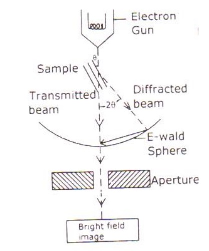
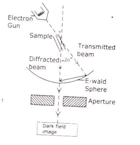
TRANSMISSION ELECTRON MICROSCOPE:
Principle:
Electrons are made to pass through the specimen and the image is formed on the fluorescent screen, either by using the transmitted beam or by using the diffracted beam.
Construction:
It consists of an electron gun to produce electrons. Magnetic condensing lens is used to condense the electrons and is also used to adjust the size of the electron that falls on to the specimen. The specimen is placed in between the condensing lens and the objective lens as shown.
The magnetic objective lens is used to block the high angle diffracted beam and the aperture is sued to eliminate the diffracted beam (if any) and in turn increases the contrast of the image.
The magnetic projector lens is placed above the fluorescent screen in order to achieve higher magnification,. The image can be recorded by using a fluorescent (Phosphor) screen or (CCD – Charged Coupled device) also.
Working:
Stream of electrons are produced by the electron gun and is made to fall over the specimen using the magnetic condensing lens.
Based on the angle of incidence the beam is partially transmitted and partially diffracted. Both these beams are recombined at the E-wald sphere to form the image. The combined image is called the phase contrast image.
In order to increase the intensity and the contrast of the image, an amplitude contrast has to be obtained. This can be achieved only by using the transmitting beam and thus the diffracted beam can be eliminated.
Now in order to eliminate the diffracted beam, the resultant beam is passed through the magnetic objective lens and the aperture. The aperture is adjusted in such a way that the diffracted image is eliminated. Thus, the final image obtained due to transmitted beam alone is passed through the projector lens for further magnification.
The magnified image is recorded in fluorescent screen or CCD. This high contrast image is called Bright Field Image.
Also, it has to be noted that the bright field image obtained is purely due to the elastic scattering (no energy change) i.e., due to transmitted beam alone.
Related Topics