Applications of Operational Amplifier - Peak Detector using Operational Amplifier | Linear Integrated Circuits : Applications of Operational Amplifier
Chapter: Linear Integrated Circuits : Applications of Operational Amplifier
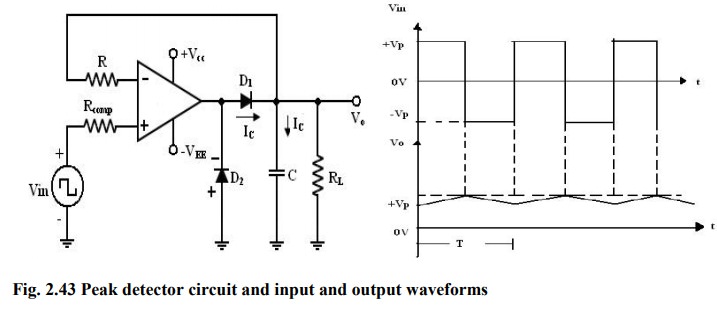
Peak Detector using Operational Amplifier
Peak
Detector
Square,
Triangular, Saw tooth and pulse waves are typical examples of non-sinusoidal
waveforms. A conventional AC voltmeter cannot be used to measure these
sinusoidal waveforms because it is designed to measure the RMS value of the
pure sine wave. One possible solution to this problem is to measure the peak
values of the non-sinusoidal waveforms. Peak detector measures the +ve peak
value of the square wave input.
i)
During the positive half cycle of Vin:
the
o/p of the op-amp drives D1 on. (Forward biased)
Charging
capacitor C to the positive peak value Vp of the input volt Vin.
ii)
During the negative half cycle of Vin:
D1
is reverse biased and voltage across C is retained.
The
only discharge path for C is through RL since the input bias IB is
negligible.
For
proper operation of the circuit, the charging time constant (CRd )
and discharging time constant (CRL) must satisfy the following
condition.
CRd
<= T/10
Where
Rd = Resistance of the forward-biased diode.
T
= time period of the input waveform.
CRL
>= 10T (2)
Where
RL = load resistor.
If
RL is very small so that eqn. (2) cannot be satisfied.
·
Use
a (buffer) voltage follower circuit between capacitor C and RL load
resistor.
·
R
is used to protect the op-amp against the excessive discharge currents.
·
Rcomp
= minimizes the offset problems caused by input current
·
D2
conducts during the –ve half cycle of Vin and prevents the op-amp from going
into negative saturation.
Note:
-ve peak of the input signal can be detected simply by reversing diode D1
and D2
Related Topics