Applications of Operational Amplifier - Integrator using Operational Amplifier | Linear Integrated Circuits : Applications of Operational Amplifier
Chapter: Linear Integrated Circuits : Applications of Operational Amplifier
Integrator using Operational Amplifier
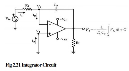
Integrator:
A
circuit in which the output voltage waveform is the integral of the input
voltage waveform is the integrator or Integration Amplifier. Such a circuit is
obtained by using a basic inverting amplifier configuration if the feedback
resistor RF is replaced by a capacitor CF.
The
expression for the output voltage V0 can be obtained by KVL eqn. at node V2.
I1
= IB + if
Since IB is negligible small,
i1=iF
Relation between current through and
voltage across the capacitor is
iC
(t) = Cdvc(t)/dt
V1=0
because A is very large,
The
output voltage can be obtained by integrating both sides
with respect to time
V0(jw)
= [1 / jwR1Cf] Vi (jw)
Indicates
that the output is directly proportional to the negative integral of the input
volts and inversely proportional to the time constant R1CF.
Ex:
If the input is sine wave -> output is cosine wave.
If
the input is square wave -> output is triangular wave.
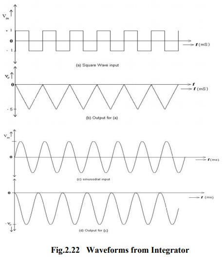
These
waveform with assumption of R1Cf = 1, Vout =0V (i.e) C
=0.
When
Vin = 0 the integrator works as an open loop amplifier because the
capacitor CF acts an open circuit to the input offset voltage Vio.
The
Input offset voltage Vio and the part of the input is charging
capacitor CF produce the error voltage at the output of the
integrator.
Practical Integrator:
Practical
Integrator to reduce the error voltage at the output, a resistor RF
is connected across the feedback capacitor CF.
Thus
RF limits the low frequency gain and hence minimizes the variations in the
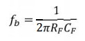
output voltages. The
frequency response of the basic integrator, shown from this fb is the frequency
at which the gain is dB and is given by
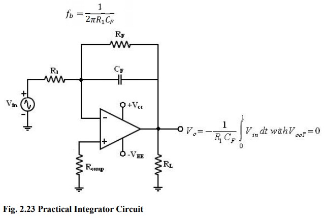
• Both
the stability and low frequency roll-off problems can be corrected by the
addition of a resistor RF in the practical integrator.
• Stability
refers to a constant gain as frequency of an input signal is varied over a
certain range.
• Low
frequency -> refers to the rate of decrease in gain roll off at lower
frequencies.
• From
the fig of practical Integrators, f is some relative operating frequency and
for frequencies f to fa to gain RF / R1 is constant. After
fa the gain decreases at a rate of 20dB/decade or between fa and fb the circuit
act as an integrator.
• The
gain limiting frequency fa is given by
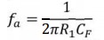
• The
value of fa and R1 CF and RF CF values should be selected
such that fa<fb.
• The
input signal will be integrated properly if the time period T of the signal is
larger than or equal to RF CF,
Uses:
Most
commonly used in
·
analog
computers
·
ADC
·
Signal
wave shaping circuits.
Related Topics