Chapter: Mechanical : Metrology and Measurements : Thread Measurement
Gear Measurement
GEAR MEASUREMENT
Introduction
Gear is a mechanical drive which
transmits power through toothed wheel. In this gear drive, the driving wheel is
in direct contact with driven wheel. The accuracy of gearing is the very
important factor when gears are manufactured. The transmission efficiency is
almost 99 in gears. So it is very important to test and measure the gears
precisely. For proper inspection of gear, it is very important to concentrate
on the raw materials, which are used to manufacture the gears, also very
important to check the machining the blanks, heat treatment and the finishing
of teeth. The gear blanks should be tested for dimensional accuracy and tooth
thickness for the forms of gears.
The
most commonly used forms of gear teeth are
1. Involute
2. Cycloidal
The involute gears also called as
straight tooth or spur gears. The cycloidal gears are used in heavy and impact
loads. The involute rack has straight teeth. The involute pressure angle is
either 20° or 14.5°.
Types of gears
1. Spur gear
Cylindrical gear whose tooth traces is
straight line. These are used for transmitting power between parallel shafts.
2.
Spiral gear
The tooth of
the gear traces curved lines.
3.
Helical gears
These gears used to transmit the power
between parallel shafts as well as nonparallel and non-intersecting shafts. It
is a cylindrical gear whose tooth traces is straight line.
4.
Bevel gears:
The tooth traces are straight-line
generators of cone. The teeth are cut on the conical surface. It is used to
connect the shafts at right angles.
5.
Worm and Worm wheel:
It
is used to connect the shafts whose axes are non-parallel and non-intersecting.
6.
Rack and Pinion:
Rack
gears are straight spur gears with infinite radius.
Gear terminology
1. Tooth profile
It
is the shape of any side of gear tooth in its cross section.
2.
Base circle
It is the circle of gear from which the involute
profile is derived. Base circle diameter Pitch circle diameter x Cosine of
pressure angle of gear
3.
Pitch circle diameter (PCD)
The diameter of a circle which will produce the same
motion as the toothed gear wheel.
4.
Pitch circle
It is the imaginary circle of gear that rolls
without slipping over the circle of its matiug gear.
5.
Addendum circle
The
circle coincides with the crests (or) tops of teeth.
6.
Dedendum circle (or) Root circle
This
circle coincides with the roots (or) bottom on teeth.
7.
Pressure angle (a)
It is the angle making by the line of action with
the common tangent to the pitch circles of mating gears.
8.
Module(m)
It is the ratio of pitch circle diameter to the
total number of teeth. Where, d = Pitch circle diameter. n = Number f teeth.
9.
Circular pitch
It is the distance along the pitch circle between
corresponding points of adjacent teeth.
10.
Addendum
Radial
distance between tip circle and pitch circle. Addendum value = 1 module.
11
Dedendum
Radial
distance between itch circle and root circle,
Dedendum
value = 1 .25module.
12.
Clearance (C)
Amount of distance made by the tip of one gear with
the root of mating gear. Clearance = Difference between Dedendum and addendum
values.
13.
Blank diameter:
The
diameter of the blank from which gear is out. Blank diameter = PCD + 2m
14.
Face:
Part
of the tooth in the axial plane lying between tip circle and pitch circle.
15.
Flank:
Part
of the tooth lying between pitch circle and root circle.
16.
Top land:
Top
surface of a tooth.
17.
Lead angle
The
angle between the tangent to the helix and plane perpendicular to the axis of
cylinder.
18. Backlash:
The
difference between the tooth thickness and the space into which it meshes. If
we assume the tooth thickness as t and width ‘ t
Gear errors
1.
Profile error:
- The maximum distance of any point on the tooth profile form to the
design profile.
2. Pitch
error: - Difference between actual and design pitch
3. Cyclic
error: - Error occurs in each revolution of gear
4.
Run out:
- Total range of reading of a fixed indicator with the contact points applied
to a surface rotated, without axial movement, about a fixed axis.
5. Eccentricity:
- Half the radial run out
6.
Wobble:
- Run out measured parallel to. the axis of rotation at a specified distance
from the axis
7.
Radial run out:
- Run out measured along a perpendicular to the axis of rotation.
8.
Undulation:
- Periodical departure of the actual tooth surface from the design surface.
9. Axial
run out: - Run out measured parallel to the axis of
rotation at a speed.
10.
Periodic error:
-Error occurring at regular intervals.
Gear Measurement
The Inspection of the gears consists of
determine the following elements in which manufacturing error may be present.
1. Runout.
2. Pitch
3. Profile
4. Lead
5. Back
lash
6. Tooth
thickness
7. Concentricity
8. Alignment
1. Runout:
It means eccentricity in the pitch
circle. It will give periodic vibration during each revolution of the gear.
This will give the tooth failure in gears. The run out is measured by means of
eccentricity testers. In the testing the gears are placed in the mandrel and
the dial indicator of the tester possesses special tip depending upon the
module of the gear and the tips inserted between the tooth spaces and the gears
are rotated tooth by tooth and the variation is noted from the dial indicator.
2.
Pitch measurement:
There
are two ways for measuring the pitch.
1. Point
to point measurement (i.e. One tooth point to next toot point)
2. Direct
angular measurement
1. Tooth
to Tooth measurement
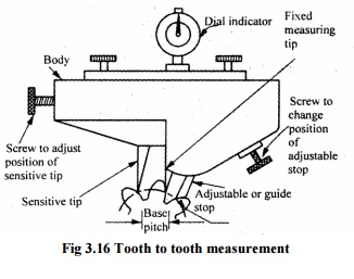
Fig 3.16 Tooth to tooth
measurement
The instrument has three
tips. One is fixed measuring tip and the second is sensitive tip, whose
position can be adjusted by a screw and the third tip is adjustable or guide
stop. The distance between the fixed and sensitive tip is equivalent to base
pitch of the gear. All the three tips are contact the tooth by setting the
instrument and the reading on the dial indicator is the error in the base
pitch.
2. Direct Angular Measurement
It is the simplest method
for measuring the error by using set dial gauge against a tooth. in this method
the position of a suitable point on a tooth is measured after the gear has been
indexed by a suitable angle. If the gear is not indexed through the angular
pitch the reading differs from the original reading. The difference between
these is the cumulative pitch error.
3. Profile checking
The methods used for
profile checking is
1. Optical projection
method.
2. Involute measuring
machine.
1.
Optical projection method:
The profile of the gear
projected on the screen by optical lens and then projected value is compared
with master profile.
2. Involute
measuring machine:
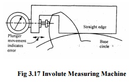
Fig
3.17 Involute Measuring Machine
In this method the gear is held on a
mandrel and circular disc of same diameter as the base circle of gear for the
measurement is fixed on the mandrel. After fixing the gear in the mandrel, the
straight edge of the instrument is brought in contact with the base circle of
the disc. Now, the gear and disc are rotated and the edge moves over the disc
without sleep. The stylus moves over the tooth profile and the error is
indicated on the dial gauge.
4. Lead checking:
It is checked by lead
checking instruments. Actually lead is the axial advance of a helix for one
complete turn. The lead checking instruments are advances a probe along a tooth
surface, parallel to the axis when the gear rotates.
5. Backlash checking:
Backlash is the
distance through which a gear can be rotated to bring its nonworking flank in
contact with the teeth of mating gear. Numerical values of backlash are
measured at the tightest point of mesh on the pitch circle.
There are two types of backlash
1. Circumferential
backlash
2. Normal
backlas
The determination of
backlash is, first one of the two gears of the pair is locked, while other is
rotated forward and backward and by the comparator the maximum displacement is
measured. The stylus of comparator is locked near the reference cylinder and a
tangent to this is called circular backlash.
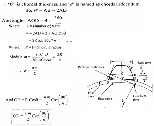
6. Tooth thickness measurement:
Tooth thickness is
generally measured at pitch circle and also in most cases the chordal thickness
measurement is carried out i.e. the chord joining the intersection of the tooth
profile with the pitch circle.
The
methods which are used for measuring the gear tooth thickness is
a) Gear
tooth vernier caliper method (Chordal thickness method)
b) Base
tangent method.
c) Constant
chord method.
d) Measurement
over pins or balls.
a) Gear tooth vernier method
In gear tooth vernier
method the thickness is measured at the pitch line. Gear tooth thickness varies
from the tip of the base circle of the tooth, and the instrument is capable of
measuring the thickness at a specified position on the tooth. The tooth vernier
caliper consists of vernier scale and two perpendicular arms. In the two
perpendicular arms one arm is used to measure the thickness and other arm is
used to measure the depth. Horizontal vernier scale reading gives chordal
thickness (W) and vertical vernier scale gives the chordal addendum. Finally
the two values compared.
The theoretical values
of W and d can be found out by considering one tooth in the gear and it can be
verified. In fig noted that w is a chord ADB and tooth thickness is specified
by AEB. The distance d is noted and adjusted on instrument and it is slightly
greater than addendum CE.
Vernier method like the
chordal thickness and chordal addendum are dependent upon the number of teeth.
Due to this for measuring large number of gears different calculations are to
be made for each gear. So these difficulties are avoided by this constant chord
method.
b) Measurement over Rolls or balls
A very good and
convenient method for measuring thickness of gear. In this method two or three
different size rollers are used for checkup the vibrations at several places on
the tooth.
7. Measurement of concentricity
In setting of gears the
centre about which the gear is mounded should be coincident with the centre
from which the gear is generated. It is easy to check the concentricity of the
gear by mounting the gear between centres and measuring the variation in height
of a roller placed between the successive teeth. Finally the variation in
reading will be a function of the eccentricity present.
8. Alignment checking
It is done by placing a
parallel bar between the gear teeth and the gear being mounted between centres.
Finally the readings are taken at the two ends of the bar and difference in
reading is the misalignment.
Parkinson Gear Tester
Working principle
The master gear is
fixed on vertical spindle and the gear to be tested is fixed on similar spindle
which is mounted on a carriage. The carriage which can slide either side of
these gears are maintained in mesh by spring pressure. When the gears are
rotated, the movement of sliding carriage is indicated by a dial indicator and
these variations arc is measure of any irregularities. The variation is
recorded in a recorder which is fitted in the form of a waxed circular chart.
In the gears are fitted on the mandrels and are free to rotate without
clearance and the left mandrel move along the table and the right mandrel move
along the spring-loaded carriage.
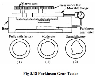
Fig
3.18 Parkinson Gear Tester
The two spindles can be adjusted so that the axial
distance is equal and a scale is attached to one side and vernier to the other,
this enables center distance to be measured to within 0.025mm. If any errors in
the tooth form when gears are in close mesh, pitch of concentricity of pitch
line will cause a variation in center distance from this movement of carriage
as indicated to the dial gauge will show the errors in the gear test. The
recorder also fitted in the form of circular or rectangular chart and the
errors are recorded.
·
Limitations of Parkinson gear tester:
1. Accuracy±0.001mm
2. Maximum
gear diameter is 300mm
3. Errors
are not clearly identified:
4. Measurement
dependent upon the master gear.
5. Low
friction in the movement of the floating carriage.
Related Topics