Chapter: Basic Electrical and electronics : Digital Electronics
Digital to Analog Converter(DAC)
DIGITAL TO ANALOG CONVERTER(DAC)
The process of converting digital signal into equivalent analog
signal is called D/A conversion. The electronics circuit, which does this
process, is called D/A converter. The circuit has „n’ number of digital data
inputs with only one output. Basically, there are two types of D/A converter
circuits: Weighted resistors D/A converter circuit and Binary ladder or R–2R
ladder D/A converter circuit.
1 Weighted resistors D/A converter
Here an
OPAMP is used as summing amplifier. There are four resistors R, 2R, 4R and 8R
at the input terminals of the OPAMP with R as feedback resistor. The network of
resistors at the input terminal of OPAMP is called as variable resistor
network. The four inputs of the circuit are D, C, B & A. Input D is at MSB
and A is at LSB. Here we shall connect 8V DC voltage as logic–1 level. So we
shall assume that 0 = 0V and 1 = 8V.
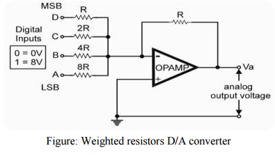
Figure:
Weighted resistors D/A converter
Now the
working of the circuit is as follows. Since the circuit is summing amplifier,
its output is given by the following equation
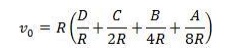
Working of the circuit
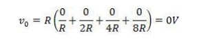
When
input DCBA = 0000, then putting these value in above equation (1) we get
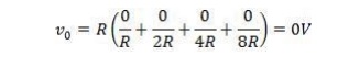
When
digital input of the circuit DCBA = 0001, then putting these value in above
equation (1) we get
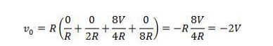
When
digital input of the circuit DCBA = 0010, then putting these value in above
equation (1) we get
…………… so
on.
In this way, when digital input changes from 0000 to 1111 (in BCD
style), output voltage (Vo) changes proportionally. This is given in the
conversion chart. There are some main disadvantages of the circuit.
They are
1) Each resistor in the circuit has different
value.
2) So error in value of each resistor adds up.
3) The value of resistor at MSB is the lowest.
Hence, it draws more current.
4) Also, its heat & power dissipation is very
high.
5) There is the problem of impedance matching due
to different values of resistors.
2 R–2R Ladder D/A Converter
It is
modern type of resistor network. It has only two values of resistors the R and
2R. These values repeat throughout in the circuit. The OPAMP is used at output
for scaling the output voltage. The working of the circuit can be understood as
follows. For simplicity, we ignore the OPAMP in the above circuit (this is
because its gain is unity). Now consider the circuit, without OPAMP. Suppose
the digital input is DCBA = 1000. Then the circuit is reduced to a small
circuit.
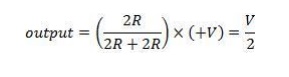
Its
output is given by –
Reduced circuit of R-2R ladder, when we
consider that all inputs=0
Now
suppose digital input of the same circuit is changed to DCBA = 0100. Then the
output voltage will be V/4, when DCBA = 0010, output voltage will be V/8, for
DCBA = 0001, output voltage will be V/16 and so on. The general formula for the
above circuit of R–2R ladder, including the OPAMP also, will be –
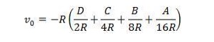
You can
take (R) common from the above formula and simplify it. With the help of this
formula, we can calculate any combination of digital input into its equivalent
analog voltage at the output terminals.
Related Topics