Chapter: Computer Networks : Physical Layer
Cable TV for Data Transfer
CABLE TV FOR DATA TRANSFER:
Cable
companies are now competing with telephone companies for the residential
customer who wants high-speed data transfer. DSL technology provides
high-data-rate connections for residential subscribers over the local loop.
1. Bandwidth
Even in
an HFC system, the last part of the network, from the fiber node to the
subscriber premises, is still a coaxial cable. This coaxial cable has a
bandwidth that ranges from 5 to 750 MHz (approximately). To provide Internet
access, the cable company has divided this bandwidth into three bands: video,
downstream data, and upstream data.
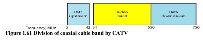
Downstream
Video Band
The
downstream video band occupies frequencies from 54 to 550 MHz. Since each TV
channel occupies 6 MHz, this can accommodate more than 80 channels.
Downstream
Data Band
The
downstream data (from the Internet to the subscriber premises) occupies the
upper band, from 550 to 750 MHz. This band is also divided into 6-MHz channels.
Modulation Downstream data band uses the 64-QAM (or possibly 256-QAM)
modulation technique. Downstream data are modulated using the 64-QAM modulation
technique.
Upstream
Data Band
The
upstream data (from the subscriber premises to the Internet) occupies the lower
band, from 5 to 42 MHz. This band is also divided into 6-MHz channels.
Modulation The upstream data band uses lower frequencies that are more
susceptible to noise and interference. For this reason, the QAM technique is
not suitable for this band.
2. CM and CMTS
To use a
cable network for data transmission, we need two key devices: a cable modem
(CM) and a cable modem transmission system (CMTS).
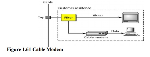
CM
The cable
modem (CM) is installed on the subscriber premises. It is similar to an ADSL.
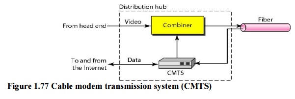
CMTS
The cable
modem transmission system (CMTS) is installed inside the distribution hub by
the cable company. It receives data from the Internet and passes them to the
combiner, which sends them to the subscriber. The CMTS also receives data from
the subscriber and passes them to the Internet. Figure 1.77 shows the location
of the CMTS.
3. Data Transmission Schemes:
DOCSIS
Several
schemes have been designed for data transmission over an HFC network.
Upstream
Communication
The
following describes the steps that must be followed by a CM:
·
The CM checks the downstream channels for a
specific packet periodically sent by the CMTS. The packet asks any new CM to
announce itself on a specific upstream channel.
·
The CMTS sends a packet to the CM, defining its
allocated downstream and upstream
·
channels.
·
The CM then starts a process, called ranging, which
determines the distance between the CM and CMTS. This process is required for
synchronization between all CMs and CMTSs for the minislots used for
timesharing of the upstream channels.
·
The CM sends a packet to the ISP, asking for the Internet
address.
·
The CM and CMTS then exchange some packets to
establish security parameters, which are needed for a public network such as
cable TV.
·
The CM sends its unique identifier to the CMTS.
·
Upstream communication can start in the allocated
upstream channel; the CM can contend for the minislots to send data.
Downstream
Communication
In the
downstream direction, the communication is much simpler. There is no contention
because there is only one sender. The CMTS sends the packet with the address of
the receiving CM, using the allocated downstream channel.
Related Topics