Chapter: Software Architectures : Documenting the Architecture
Unified Modeling Language(UML)
WHY THE ARCHITECTURE IS THE WAY IT IS: RATIONALE
Similar
in purpose to the rationale for a view or the rationale for an interface
design, cross-view rationale explains how the overall architecture is in fact a
solution to its requirements. One might use the rationale to explain
·
the implications of system-wide design choices on
meeting the requirements or satisfying constraints.
·
the effect on the architecture when adding a foreseen
new requirement or changing an existing one.
·
the constraints on the developer in implementing a
solution.
·
decision alternatives that were rejected.
In
general, the rationale explains why a decision was made and what the
implications are in changing it.
Unified Modeling Language
We
have concentrated on the kind of information that should be included in
architecture documentation. Architecture in some sense expresses what is
essential about a software system, and that essence is independent of languages
and notations to capture it. Nevertheless, today the Unified Modeling Language
(UML) has emerged as the de facto standard notation for documenting a software
architecture. However, it must be said that UML makes its main contribution in
a view's primary presentation, and its secondary contribution in the behavior
of an element or group of elements. It is up to the architect to augment the
UML pictures with the necessary supporting documentation (the element catalog,
the rationale, and so forth) that a responsible job requires. UML provides no
direct support for components, connectors, layers, interface semantics, or many
other aspects of a system that are supremely architectural.
Still,
in most cases we can use the constructs that UML does offer to achieve
satisfactory effects, at least in crafting the primary presentations of
architectural views. We begin by discussing module views.
MODULE VIEWS
Recall
that a module is a code or implementation unit and a module view is an
enumeration of modules together with their interfaces and their relations.
Interfaces
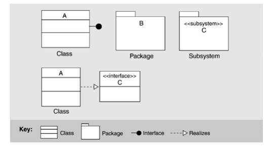
Figure
9.4 shows how
module interfaces can be represented in UML. UML uses a "lollipop"
to denote an interface, which can be appended to classes and subsystems, among
other things.
UML
also allows a class symbol (box) to be stereotyped as an interface; the
open-headed dashed arrow shows that an element realizes an interface. The
bottom of the class symbol can be annotated with the interface's signature
information: method names, arguments, argument types, and so forth. The
lollipop notation is normally used to show dependencies from elements to the
interface, while the box notation allows a more detailed description of the
interface's syntax, such as the operations it provides.
Modules
UML
provides a variety of constructs to represent different kinds of modules. Figure 9.5 shows some
examples. UML has a class construct, which is the object-oriented specialization
of a module. Packages can be used in cases where grouping of functionality is
important, such as to represent layers and classes. The subsystem construct can
be used if a specification of interface and behavior is required.
Figure 9.5. Examples of module notations in UML
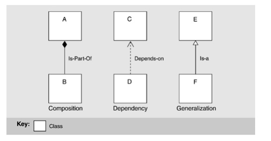
Figure
9.6 shows how
the relations native to module views are denoted using UML. Module
decomposition relies on the "is-part-of" relation. The module uses
view relies on the dependency relation, and the module class view relies on the
generalization, or "is-a" relation (also called
"inheritance").
Figure 9.6. Examples of relation notations in UML. Module B is part of
module A, module D depends on module C, and module F is a type of module E.
Aggregation
In
UML, the subsystem construct can be used to represent modules that contain
other modules; the class box is normally used for the leaves of the
decomposition. Subsystems are used both as packages and as classifiers. As
packages, they can be decomposed and hence are suitable for module aggregation.
As classifiers, they encapsulate their contents and can provide an explicit
interface. Aggregation is depicted in one of three ways in UML:
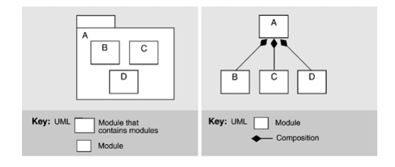
·
Modules may be nested (see Figure
9.7 left).
Figure 9.7. Decomposition in UML with nesting. The aggregate module is
shown as a package (left);
decomposition in UML with arcs (right).
·
A succession of two diagrams (possibly linked) can be
shown, where the second is a depiction of the contents of a module shown in the
first.
·
An arc denoting composition is drawn between the parent
and the children (see Figure
9.7 right).
In UML,
composition is a form of aggregation with implied strong ownership-that is,
parts live and die with the whole. If module A is composed of modules B and C,
then B or C cannot exist without A, and if A is destroyed at runtime, so are B
and C. Thus, UML's composition relation has implications beyond the structuring
of the implementation units; the relation also endows the elements with a
runtime property. As an architect, you should make sure you are comfortable
with this property before using UML's composition relation.
Generalization
Expressing
generalization is at the heart of UML in which modules are shown as classes
(although they may also be shown as subsystems). Figure
9.8 shows the basic notation available in UML.
Figure 9.8. Documenting generalization in UML with two line styles
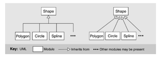
The
two diagrams in Figure
9.8 are semantically identical. UML allows an ellipsis (…)
in place of a submodule, indicating that a module can have more children than
shown and that additional ones are likely. Module Shape is the parent of
modules Polygon, Circle, and Spline, each of which is a subclass, child, or
descendant of Shape. Shape is more general, while its children are specialized
versions.
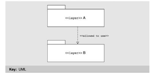
Dependency
The
basic notation for dependency was shown in Figure
9.6. The most architecturally significant manifestation of
dependency is found in layers. Sadly, UML has no built-in primitive
corresponding to a layer. However, it can represent simple layers using packages, as shown in Figure
9.9. These are general-purpose mechanisms for organizing
elements into groups. UML has predefined packages for systems and subsystems.
We can introduce an additional package for layers by defining it as a package
stereotype. A layer can be shown as a UML package with the constraints that it
groups modules together and that the dependency between packages is
"allowed to use." We can designate a layer using the package notation
with the stereotype name <<layer>>
preceding the layer name, or introduce a new visual form, such as a shaded
rectangle.
Figure 9.9. A simple representation of layers in UML
Related Topics