Chapter: Software Architectures : Documenting the Architecture
Documenting a View
Documenting
a View
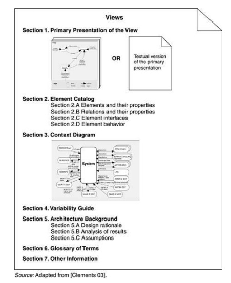
There is no industry-standard template for documenting a
view, but the seven-part standard organization that we suggest in this section
has worked well in practice. First of all, whatever sections you choose to
include, make sure to have a standard
organization. Allocating specific information to specific sections will help
the documentation writer attack the task and recognize completion, and it will
help the documentation reader quickly find information of interest at the
moment and skip everything else.
1.
Primary presentation shows the elements and the
relationships among them that populate
the view. The primary presentation should contain the information you wish to
convey about the system (in the vocabulary of that view) first. It should
certainly include the primary elements and relations of the view, but under
some circumstances it might not include all of them. For example, you may wish
to show the elements and relations that come into play during normal operation,
but relegate error handling or exceptional processing to the supporting
documentation.
The primary presentation is
usually graphical. In fact, most graphical notations make their contributions
in the form of the primary presentation and little else. If the primary presentation
is graphical, it must be accompanied by a key that explains, or that points to
an explanation of, the notation or symbology used.
Sometimes the primary
presentation can be tabular; tables are often a superb way to convey a large
amount of information compactly.
A textual presentation still
carries the obligation to present a terse summary of the most important
information in the view.
2.
Element catalog details at least those elements
and relations depicted in the primary
presentation, and perhaps others. Producing the primary presentation is often
what architects concentrate on, but without backup information that
explains the picture, it is of
little value. For instance, if a diagram shows elements A, B, and C, there had
better be documentation that explains in sufficient detail what A, B, and C
are, and their purposes or the roles they play, rendered in the vocabulary of
the view. For example, a module decomposition view has elements that are
modules, relations that are a form of "is part of," and properties
that define the responsibilities of each module. A process view has elements
that are processes, relations that define synchronization or other
process-related interaction, and properties that include timing parameters.
In addition, if there are
elements or relations relevant to the view that were omitted from the primary
presentation, the catalog is where those are introduced and explained.
The behavior and interfaces of
elements are two other aspects of an element catalog; these will be discussed
shortly.
3. Context diagram shows how the system depicted in the view relates to its environment in the vocabulary of the
view. For example, in a component-and- connector view you show which component
and connectors interact with external components and connectors, via which
interfaces and protocols.
4.
Variability guide shows how to exercise any
variation points that are a part of the architecture
shown in this view. In some architectures, decisions are left unbound until a
later stage of the development process, and yet the architecture must still be
documented. An example of variability is found in software product lines where
the product line architecture is suitable for multiple particular systems
. A variability guide should
include documentation about each point of variation in the architecture,
including
-
the options among which a choice is to be made. In a module
view, the options are the various versions or parameterizations of modules. In
a component-and-connector view, they might include constraints on replication,
scheduling, or choice of protocol. In an allocation view, they might include
the conditions under which a software element would be allocated to a
particular processor.
-
the binding time of the option. Some choices are made at design
time, some at build time, and others at runtime.
5.
Architecture background explains why the design
reflected in the view came to be. The
goal of this section is to explain to someone why the design is as it is and to
provide a convincing argument that it is sound. An architecture background
includes
-
rationale, explaining why the decisions reflected in the view
were made and why alternatives were rejected.
-
analysis results, which justify the design or explain what would
have to change in the face of a modification.
-
assumptions reflected in the design.
6.
Glossary of terms used in the views, with a brief
description of each.
7.
Other information. The precise contents of this
section will vary according to the standard
practices of your organization. They might include management information such
as authorship, configuration control data, and change histories. Or the
architect might record references to specific sections of a requirements
document to establish traceability. Strictly speaking, information such as this
is not architectural. Nevertheless, it is convenient to record it alongside the
architecture, and this section is provided for that purpose. In any case, the
first part of this section must detail its specific contents.
Figure 9.1. The seven
parts of a documented view

Related Topics