Chapter: Software Architectures : Documenting the Architecture
Allocation Views
ALLOCATION VIEWS
In
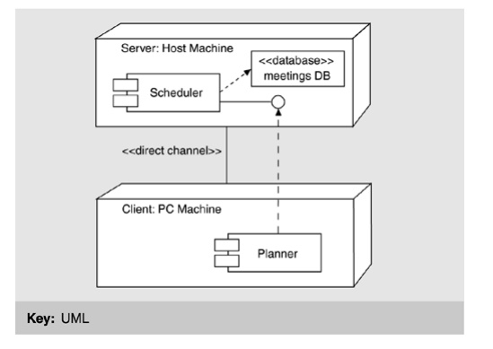
UML, a deployment diagram is a graph of nodes connected by communication
associations. Figure
9.13 provides an example. Nodes may contain component
instances, which indicates that the component lives or runs on the node.
Components may contain objects, which indicates that the object is part of the
component. Components are connected to other components by dashed-arrow
dependencies (possibly through interfaces). This indicates that one component
uses the services of another; a stereotype may be used to indicate the precise
dependency if needed. The deployment type diagram may also be used to show
which components may run on which nodes, by using dashed arrows with the
stereotype «supports».
Figure 9.13. A deployment view in UML

A node
is a runtime physical object that represents a processing resource, generally
having at least a memory and often processing capability as well. Nodes include
computing devices but also human or mechanical processing resources. Nodes may
represent types of instances. Runtime computational instances, both objects and
components, may reside on node instances.
Nodes
may be connected by associations to other nodes. An association indicates a
communication path between them. The association may have a stereotype to indicate
the nature of the communication path (for example, the kind of channel or
network).
The
nesting of symbols within the node symbol signifies a composition association
between a node class and constituent classes or a composition link between a
node object and constituent objects.
Related Topics