Chapter: VLSI Design : Specification Using Verilog HDL
Timing Controls - Verilog HDL
TIMING CONTROLS
A timing
control is either a delay control or an event control.
1. Delay control:
A delay
control delays an assignment by a specified amount of time. A timescale
compiler directive is used to specify the units of time followed by the
precision used to calculate time expressions, `timescale 1ns/10ps // Units of
time are ns. Round times to 10 ps.
Time
units may only be s , ns , ps , or fs and the multiplier must be 1, 10, or 100.
We can delay an assignment in two different ways:
·
Sample the RHS immediately and then delay the
assignment to the LHS.
·
Wait for a specified time and then assign the value
of the LHS to the RHS.
Here is
an example of the first alternative (an intra-assignment delay):
a = #1 b;
// intra-assignment delay
The
second alternative is delayed assignment:
#1 a = b;
// delayed assignment
These two
alternatives are not the same. The intra-assignment delay is equivalent to the
following code:
begin //
Equivalent to intra-assignment delay. hold = b; // Sample and hold y
immediately.
#1; //
Delay.
a = hold;
// Assignment to a. Overall same as a = #1 b. end
In
contrast, the delayed assignment is equivalent to a delay followed by an
assignment as follows:
begin //
Equivalent to delayed assignment.
#1; //
Delay.
a = b; //
Assign y to x. Overall same as #1 a = b. end
2. Event control:
An event
control, delays an assignment until a specified event occurs. Here is the
formal definition:
event_control
::= @ event_identifier | @ (event_expression)
event_expression
::= expression | event_identifier
| posedge
expression | negedge expression
|
event_expression or event_expression
A
positive edge (denoted by the keyword posedge ) is a transition from '0' to '1'
or 'x' , or a transition from 'x' to '1 '. A negative edge ( negedge ) is a
transition from '1' to '0' or 'x' , or a transition from 'x' to '0'.
Transitions to or from 'z' do not count. Here are examples of event controls:
moduledelay_controls;
reg X, Y, Clk, Dummy;
always #1
Dummy=!Dummy; // Dummy clock, just for graphics.
//
Examples of delay controls:
always
begin #25 X=1;#10 X=0;#5; end
// An
event control:
always
@(posedgeClk) Y=X; // Wait for +ve clock edge. always #10 Clk = !Clk; // The
real clock.
initial
begin Clk = 0;
$display("T Clk X Y");
$monitor("%2g",$time,,,Clk,,,,X,,Y);
$dumpvars;#100
$finish; end endmodule
T Clk X Y
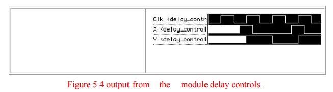
The dummy
clock in delay_controls helps in the graphical waveform display of the results
(it provides a one-time-tick timing grid when we zoom in, for example). Figure
shows the graphical output (white is used to represent the initial unknown
values). The assignment statements to 'X' in the always statement repeat (every
25 + 10 + 5 = 40 time ticks).
Events
can be declared (as named events), triggered, and detected as follows:
moduleshow_event;
reg
clock;
event
event_1, event_2; // Declare two named events.always @(posedge clock) ->
event_1; // Trigger event_1. always @ event_1
begin
$display("Strike 1!!"); -> event_2; end // Trigger event_2. always
@ event_2 begin $display("Strike 2!!");
$finish;
end // Stop on detection of event_2. always #10 clock = ~ clock; // We need a
clock. initial clock = 0;
end module
Related Topics