Chapter: VLSI Design : Specification Using Verilog HDL
Testbenches
TESTBENCHES
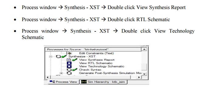
Synthesis our design, from the
source window select, Synthesis/ implementation from the window Now double
click the Synthesis –XST.
After the HDL synthesis phase of
the synthesis process, you can display a schematic representation of our
synthesized source file.
§ This
schematic shows a representation of the pre-optimized design in terms of
generic symbols, such as adders, multipliers, counters, AND gates, and OR gates
àdouble click View RTL Schematic.
§ Double
click the schematic to internal view.
§ Double
click outside the schematic to move one-level back.
§ This
schematic shows a representation of the design in terms of logic elements
optimized to the target device.
§ For
example, in terms of LUTs(Look Up Table), carry logic, I/O buffers, and other
technology-specific components à Double
click View Technology Schematic.
§ Double
click the schematic to inner view.
§ Double
click the LUT to inner view. This is Gate Level view of LUT, if we want see
Truth Table and K-Map for our design just click the respective tabs.
§ After
finishing the synthesis, we can view number of Slices, LUT (Look Up Table),
I/Os are taken by our deign in Device using Design summary.
Example MUX Description Using Case
Statement
module
mux4 (s a, b, c, d, y);
input
[1:0] s;
input
[1:0] a, b, c, d;
output
[1:0] y;
reg [1:0]
y;
always
@(s or a or b or c or d)
begin
case (s)
2'b00: y
= a;
2'b01: y
= b;
2'b10: y
= c; default:y = d; endcase
endendmodule
The
preceding Case statement will evaluate the values of the input s in priority
order. To avoid priority processing, it is recommended that you use a
parallel-case Verilog meta comment which will ensure parallel evaluation of the
sel inputs as in the following.
Example:
always
@(sel or a or b or c or d) //synthesis parallel_case
For and Repeat loops
When
using always blocks, repetitive or bit slice structures can also be described
using the "for" statement or the "repeat" statement.
The
"for" statement is supported for:
Constant bounds
Stop test condition using
operators <, <=, > or >=
Next step computation falling in
one of the following specifications:
o var =
var + step
o var =
var – step
(wherevar
is the loop variable and step is a constant value).
The
repeat statement is only supported for constant values. The following example
shows the use of a
For Loop.
Example For Loop Description
modulecountzeros
(a, Count); input [7:0] a;
output
[2:0] Count; reg [2:0] Count;
reg [2:0]
Count_Aux; integer i;
always
@(a) begin
Count_Aux
= 3'b0;
for (i =
0; i < 8; i = i+1) begin
if
(!a[i])
Count_Aux
= Count_Aux+1; end
Count =
Count_Aux;
endendmodule
Related Topics