Chapter: Mechanical : Metrology and Measurements : Measurement of Power, Flow and Temperature Related Properties
Thermoresistive Temperature Measuring Devices
THERMORESISTIVE
TEMPERATURE MEASURING DEVICES
Principle of operation
·
A change in temperature causes the electrical
resistance of a material to change.
·
The resistance change is measured to
infer the temperature change.
·
There are two types of thermoresistive
measuring devices: resistance temperature detectors and thermistors, both of
which are described here.
Resistance temperature detectors
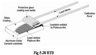
A resistance temperature detector (abbreviated RTD)
is basically either a long, small diameter metal wire (usually platinum) wound
in a coil or an etched grid on a substrate, much like a strain gauge.

The resistance of an RTD increases with increasing
temperature, just as the resistance of a strain gage increases with increasing
strain. The resistance of the most common RTD is 100 Ω at 0ºC.

If the temperature
changes are large, or if precision is not critical, the RTD resistance can be
measured directly to obtain the temperature. If the temperature changes are
small, and/or high precision is needed, an electrical circuit is built to
measure a change in resistance of the RTD, which is then used to calculate a
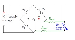
change in temperature. One simple circuit is the quarter bridge Wheatstone
bridge circuit, here called a two-wire RTD bridge circuit
Rlead
represents the resistance of one of the wires (called lead wires) that run from
the bridge to the RTD itself. Lead resistance is of little concern in strain
gage circuits because Rlead remains constant at all times, and we
can simply adjust one of the other resistors to zero the bridge.
For RTD circuits, however, some portions of the lead
wires are exposed to changing temperatures. Since the resistance of metal wire
changes with temperature, Rlead changes with T and this can cause
errors in the measurement. This error can be non-trivial changes in lead
resistance may be misinterpreted as changes in RTD resistance, and therefore
give a false temperature measurement.
Thermistors
A thermistor is similar
to an RTD, but a semiconductor material is used instead of a metal. A
thermistor is a solid state device. Resistance thermometry may be performed
using thermistors. Thermistors are many t useful over limited ranges of
temperature. They are small pieces of ceramic material made by sintering
mixtures of metallic oxides of Manganese, Nickel, Cobalt, Copper and Iron etc.

Resistance of a
thermistor decreases non-linearly with temperature. Thermistors are extremely
sensitive but over a narrow range of temperatures. A thermistor has larger
sensitivity than does an RTD, but the resistance change with temperature is
nonlinear, and therefore temperature must be calibrated with respect to
resistance. Unlike RTDs, the resistance of a thermistor decreases with
increasing temperature. The upper temperature limit of thermistors is typically
lower than that of RTD. However, thermistors have greater sensitivity and are
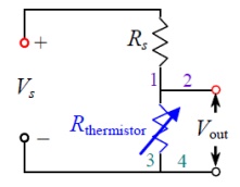
typically more accurate than RTDs or thermocouples. A simple voltage divider,
where Vs is the supply voltage and Rs is a fixed (supply) resistor. Rs and Vs
can be adjusted to obtain a desired range of output voltage Vout for a given
range of temperature. If the proper value of Rs is used, the output voltage is
nearly (but not exactly) linear with temperature. Some thermistors have 3 or 4
lead wires for convenience in wiring –two wires are connected to one side and
two to the other side of the thermistor (labeled 1, 2 and 3, 4 above).
Related Topics