Chapter: Mechanical : Metrology and Measurements : Measurement of Power, Flow and Temperature Related Properties
Scale and balances on Measurement of Force
Scale and balances
a. Equal arm balance
An equal arm balance works on the principle of moment comparison. The beam of the equal arm balance is in equilibrium position when,
Clockwise rotating moment = Anti-clockwise rotating moment M2L2 = M1L1
That is, the unknown force is balanced against the known gravitational force.
Description
The main parts of the arrangement are a follows:
· A beam whose centre is pivoted and rests on the fulcrum of a knife edge. Either side of the beam is equal in length with respect to the fulcrum
· A pointer is attached to the center of the beam. This pointer will point vertically downwards when the beam is in equilibrium.
· A Provision to place masses at either end of the beam.
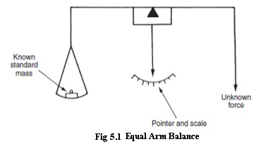
Operation
• A known standard mass (m1) is placed at one end of the beam and an unknown mass (m2) is placed at its other end.
• Equilibrium condition exists when, clockwise rotating moment = Anti- clockwise rotating moment
· Moreover at a given location, the ear masses (m1 and m2) and hence at equilibrium condition. W1=W2. That is, the
unknown force (weight) will be equal to the known force (weight).
b. Unequal arm balance
An unequal arm balance works on the principle of moment comparison.
The beam of the unequal arm balance is in equilibrium position when,
Clockwise rotating moment = Anti-clockwise rotating moment
F x L2 = Fx x L1
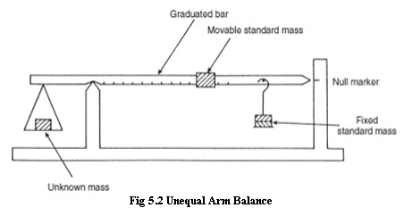
Description
The main parts of the arrangements are as follows:
· A graduated beam pivoted to a knife ed
· A leveling pointer is attached to the beam
· A known mass “m” is attached to the r unknown forcem”“F”can. Thisslidemasson the“ right
· Provisions are made tox” applyontheanleftunknos beam.
Operation
· An unknown force “Fx” is applied on t edge “Z” as shown
· Now the positi”on theof massright“mside of th the leveling pointer reads null balance position. When the leveling pointer is
in null balance position, the beam is in equilibrium.
Clock wise rotating moment = Anti-clock wise rotating moment
Fx.L1 = F. L2
Fx = Mg.L2/L1
· Thus the unknownx”is proportionalforce“F2”oftothethemad “m” from the knife edge “Y”
· The right hand side of the beam which is graduated is calibrated to get a direct
measurex” of “F
c. Pendulum Scale(Multi-lever Type)
It is a moment comparison device. The unknown force is converted to torque which is then balanced by the torque of a fixed standard mass arranged as a pendulum.
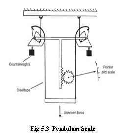
Description
• The scale’s frames carry support ribb These support ribbons are attached to the sectors. The loading ribbons are attached to the sectors and the load rod a shown. The load rod is inturn attached to the weighing platform.
• The two sectors are connected on either side of an equalizer beam. The sectors carry counter weighs. To the center of the equalizer beam is attached a rack and pinion arrangement.
• A pointer is attached to the pinion which sweeps over a weight (force) calibrated scale.
Operation
· The unknown force is applied to the load rod. Due to this force, the loading tapes are pulled downwards. Hence the loading tapes rotate the sectors.
· As the sectors rotate about the pivots, it moves the counter weights outwards, This movements increases the counter weight effective moment until the torque produced by the force applied to the load rod and the moment produced by the counter weight balance each other, thereby establishing an equilibrium.
· During the process of establishing equilibrium, the equalizer beam would be displaced downwards. As the rack is attached to the equalizer beam, the rack also is displaced downwards rotating the pinion.
· As the pointer is attached to the pinion, the rotation of the pinion makes the pointer to assume a new position on the scale. The scale is calibrated to read the weight directly. Thus the force applied on the load rod is measured.
Related Topics