Chapter: Mechanical : Metrology and Measurements : Measurement of Power, Flow and Temperature Related Properties
Flow Measurements
FLOW MEASUREMENTS
The flow rate of a fluid flowing in a
pipe under pressure is measured for a variety of applications, such as
monitoring of pipe flow rate and control of industrial processes. Differential
pressure flow meters, consisting of orifice, flow nozzle, and venturi meters,
are widely used for pipe flow measurement and are the topic of this course. All
three of these meters use a constriction in the path of the pipe flow and
measure the difference in pressure between the undisturbed flow and the flow
through the constriction. That pressure difference can then be used to
calculate the flow rate. Flow meter is a device
that measures the rate of flow or quantity
of a moving fluid in an open or closed conduit.
Flow measuring devices are generally classified into four groups.
They are
1. Mechanical type flow
meters
Fixed restriction variable
head type flow meters using different sensors like orifice plate, venturi tube,
flow nozzle, pitot tube, dall tube, quantity meters like positive displacement
meters, mass flow meters etc. fall under mechanical type flow meters.
2. Inferential type flow
meters
Variable area flow meters
(Rotameters), turbine flow meter, target flow meters etc.
3. Electrical type flow
meters
Electromagnetic flow
meter, Ultrasonic flow meter, Laser doppler Anemometers etc. fall under
electrical type flow meter.
4. Other flow meters
Purge flow regulators,
Flow meters for Solids flow measurement, Cross-correlation flow meter, Vortex
shedding flow meters, flow switches etc.
Orifice
Flow Meter
An Orifice flow meter is
the most common head type flow measuring device. An orifice plate is inserted
in the pipeline and the differential pressure across it is measured.
Principle of Operation
The orifice plate inserted in the
pipeline causes an increase in flow velocity and a corresponding decrease in
pressure. The flow pattern shows an effective decrease in cross section beyond
the orifice plate, with a maximum velocity and minimum pressure at the
venacontracta.
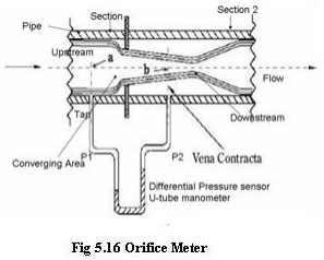
The flow pattern and the sharp leading
edge of the orifice plate which produces it are of major importance. The sharp
edge results in an almost pure line contact between the plate and the effective
flow, with the negligible fluid-to-metal friction drag at the boundary.
Types of Orifice Plates
The simplest form of
orifice plate consists of a thin metal sheet, having in it a square edged or a
sharp edged or round edged circular hole.
There are three types of orifice plates namely
1. Concentric
2. Eccentric and
3. Segmental type.
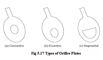
The concentric type is
used for clean fluids. In metering dirty fluids, slurries and fluids containing
solids, eccentric or segmental type is used in such a way that its lower edge
coincides with the inside bottom of the pipe. This allows the solids to flow
through without any obstruction. The orifice plate is inserted into the main
pipeline between adjacent flanges, the outside diameters of the plate being
turned to fit within the flange bolts. The flanges are either screwed or welded
to the pipes.
Applications
The concentric orifice plate is used
to measure flow rates of pure fluids and has a wide applicability as it has
been standardized
·
The eccentric and
segmental orifice plates are used to measure flow rates of fluids containing
suspended materials such as solids, oil mixed with water and wet steam.
Advantages
·
It is very cheap and easy
method to measure flow rate
·
It has predictable characteristics
and occupies less space
·
Can be used to measure
flow rates in large pipes
Limitations
· The vena-contracta length depends on the roughness of the inner
wall of the pipe and sharpness of the orifice plate. In certain case it becomes
difficult to tap the minimum pressure due the above factor
· Pressure recovery at downstream is poor, that is, overall loss
varies from 40 to 90% of the differential pressure.
· In the upstream straightening vanes are a must to obtain laminar
flow conditions.
· The orifice plate gets corroded and due to this after sometime,
inaccuracy occurs. The coefficient of discharge is low.
Venturi
Meter
General performance and calculations
are similar to those for orifice plates. In these devices, there is a
continuous contact between the fluid flow and the surface of the primary
device.
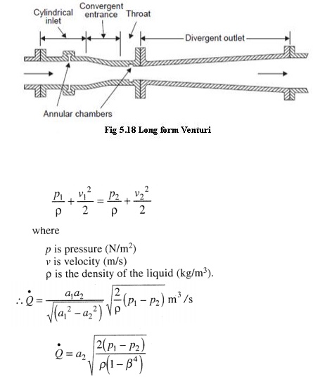
It consists of a cylindrical inlet
section equal to the pipe diameter, a converging conical section in which the
cross sectional area decreases causing the velocity to increase with a
corresponding increase in the velocity head and a decrease in the pressure
head; a cylindrical throat section where the velocity is constant so that the
decreased pressure head can be measured and a diverging recovery cone where the
velocity decreases and almost all of the original pressure head is recovered. The
unrecovered pressure head is commonly called as head loss.
Limitations
This flow meter
is limited to use on
clean, non- corrosive liquids and
gases, because it is impossible to clean out or flush out the pressure taps if
they clog up with dirt or debris.
Short Form Venturi Tubes
In an effort to reduce costs and
laying length, manufactures developed a second generation, or short-form
venturi tubes shown in Figure 5.19.
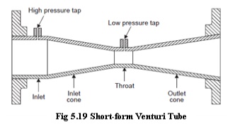
There were two major differences in this design. The
internal annular chamber was replaced by a single pressure tap or in some cases
an external pressure averaging chamber, and the recovery cone angle was
increased from 7 degrees to 21 degrees. The short form venture tubes can be
manufactured from cast iron or welded from a variety of materials compatible
with the application.
The pressure taps are located one-quarter to
one-half pipe diameter upstream of the inlet cone and at the middle of the
throat section. A piezometer ring is sometimes used for differential pressure
measurement. This consists of several holes in the plane of the tap locations.
Each set of holes is connected together in an annular ring to give an average
pressure. Venturis with piezometer connections are unsuitable for use with
purge systems used for slurries and dirty fluids since the purging fluid tends
to short circuit to the nearest tap holes. Piezometer connections are normally
used only on very large tubes or where the most accurate average pressure is
desired to compensate for variations in the hydraulic profile of the flowing
fluid. Therefore, when it is necessary to meter dirty fluids and use piezometer
taps, sealed sensors which mount flush with the pipe and throat inside wall
should be used. Single pressure tap venturis can be purged in the normal manner
when used with dirty fluids. Because the venturi tube has no sudden changes in
contour, no sharp corners, and no projections, it is often used to measure
slurries and dirty fluids which tend to build up on or clog of the primary
devices.
Flow
Nozzle
Flange Type Flow Nozzle
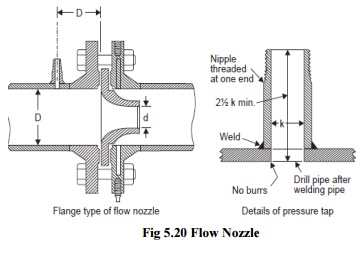
The Flow nozzle is a smooth, convergent section that
discharges the flow parallel to the axis of the downstream pipe. The downstream
end of a nozzle approximates a short tube and has the diameter of the
venacontracta of an orifice of equal capacity. Thus the diameter ratio for a
nozzle is smaller or its flow coefficient is larger. Pressure recovery is
better than that of an orifice. Figure shows a flow nozzle of flange type.
Advantages
1. Permanent pressure loss lower than that for an orifice plate.
2. It is suitable for fluids containing solids that settle.
3. It is widely accepted for high pressure and temperature steam
flow.
Disadvantages
1. Cost is higher than orifice plate.
2. It is limited to moderate pipe sizes, it requires more
maintenance.
Pitot
tube
An obstruction type
primary element used mainly for fluid velocity measurement is the Pitot tube.
Principle
Consider Figure which shows flow
around a solid body. When a solid body is held centrally and stationary in a
pipeline with a fluid streaming down, due to the presence of the body, the
fluid while approaching the object starts losing its velocity till directly in
front of the body, where the velocity is zero. This point is known as the
stagnation point. As the kinetic head is lost by the fluid, it gains a static
head. By measuring the difference of
pressure between that at normal flow line and that at the stagnation point, the velocity is found out.
This principle is used in pitot tube sensors.
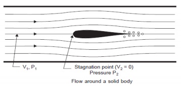
Fig 5.21 Flow through solid body
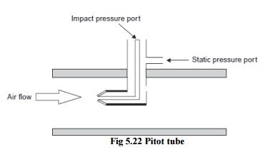
Fig 5.22 Pitot tube
A common industrial type of pitot tube
consists of a cylindrical probe inserted into the air stream, as shown in
Figure. Fluid flow velocity at the upstream face of the probe is reduced
substantially to zero. Velocity head is converted to impact pressure, which is
sensed through a small hole in the upstream face of the probe. A corresponding
small hole in the side of the probe senses static pressure. A pressure
instrument measures the differential pressure, which is proportional to the
square of the stream velocity in the vicinity of the impact pressure sensing
hole.
The velocity equation for the pitot
tube is given by,

Advantages
1. No pressure loss.
2. It is relatively simple.
3. It is readily adapted for flow measurements made in very large
pipes or ducts
Disadvantages
1. Poor accuracy.
2. Not suitable for dirty or sticky fluids and fluids containing
solid particles.
3. Sensitive to upstream disturbances.
Rotameter
The orificemeter, Venturimeter and flow
nozzle work on the principle of constant area variable pressure drop. Here the
area of obstruction is constant, and the pressure drop changes with flow rate.
On the other hand Rotameter works as a constant pressure drop variable area
meter. It can be only be used in a vertical pipeline. Its accuracy is also less
(2%) compared to other types of flow meters. But the major advantages of
rotameter are, it is simple in construction, ready to install and the flow rate
can be directly seen on a calibrated scale, without the help of any other
device, e.g. differential pressure sensor etc. Moreover, it is useful for a
wide range of variation of flow rates (10:1).
The basic construction of a rotameter is shown in
figure. It consists of a vertical pipe, tapered downward. The flow passes from
the bottom to the top. There is cylindrical type metallic float inside the
tube. The fluid flows upward through the gap between the tube and the float. As
the float moves up or down there is a change in the gap, as a result changing
the area of the orifice. In fact, the float settles down at a position, where
the pressure drop across the orifice will create an upward thrust that will
balance the downward force due to the gravity. The position of the float is
calibrated with the flow rate.
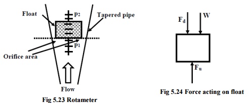
Fig
5.23 Rotameter
γ1=
Specific weight of the float
γ2=
specific weight of the fluid
ν= volume of the float
Af= Area of the float.
At= Area of the tube at equilibrium
(corresponding to the dotted line)

Fd = Downward thrust on the float Fu
= Upward thrust on the float
The major source of error in rotameter
is due to the variation of density of the fluid. Besides, the presence of
viscous force may also provide an additional force to the float.
Applications
·
Can be used to measure flow rates of
corrosive fluids
·
Particularly useful to measure low flow
rates
Advantages
·
Flow conditions are visible
·
Flow rate is a linear function(uniform
flow scales)
·
Can be used to measure flow rates of
liquids, gases and vapour
·
By changing the float, tapered tube or
both, the capacity of the rotameter can be changed.
Limitations
· They
should be installed vertically
· They
cannot be used for measurements in moving objects
· The
float will not be visible when coloured fluids are used, that is, when opaque
fluid are used.
· For
high pressure and temperature fluid flow measurements, they are expensive
· They cannot be used for fluids containing high percentage of solids in suspension.
Related Topics