Chapter: Linear Integrated Ciruits : Application of ICs
Spark Firing Circuit
Spark Firing Circuit:
The
"coil" used to generate the spark voltage is actually a transformer,
with a very high secondary- to-primary turns ratio. When the points first
close, current starts to flow in the primary winding and eventually reaches the
final value set by the 12V battery and the current limiting resistor. At this
time, the current flow is a fixed DC value, which means no voltage is generated
across either winding of the transformer.
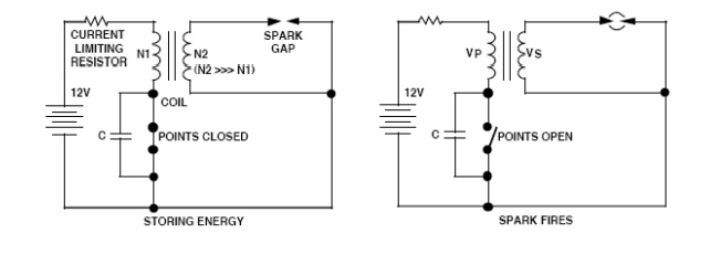
When the
points open, the current in the primary winding collapses very quickly, causing
a large voltage to appear across this winding. This voltage on the primary is
magnetically coupled to (and stepped up by) the secondary winding, generating a
voltage of 30 kV - 40 kV on the secondary side. As explained previously, the
law of inductance says that it is not possible to instantly break the current
flowing in an inductor (because an infinite voltage would be required to make
it happen).
This
principle is what causes the arcing across the contacts used in switches that
are in circuits with highly inductive loads. When the switch just begins to
open, the high voltage generated allows electrons to jump the air gap so that
the current flow does not actually stop instantly. Placing a capacitor across
the contacts helps to reduce this arcing effect. In the automobile ignition, a
capacitor is placed across the points to minimize damage due to arcing when the
points "break" the current flowing in the low-voltage coil winding
(in car manuals, this capacitoris referred to as a "condenser").
Related Topics