Chapter: Linear Integrated Ciruits : Application of ICs
Power Audio Amplifier IC LM380
POWER AUDIO AMPLIFIER IC LM380:
Features of LM380:
1.
Internally fixed gain of 50 (34dB)
2.
Output is automatically self centring to one half
of the supply voltage.
3.
Output is short circuit proof with internal thermal
limiting.
4.
Input stage allows the input to be ground
referenced or ac coupled.
5.
Wide supply voltage range (5 to 22V).
6.
High peak current capability.
7.
High impedence.
8.
Low total harmonic distortion
9.
Bandwidth of 100KHz at Pout = 2W & RL = 8Ω
Introduction:
Small
signal amplifier are essentially voltage amplifier that supply their loads with
larger amplifier signal voltage. On the other hand , large signal or power
amplifier supply a large signal current to current operated loads such as
speakers & motors. In audio applications, however, the amplifier called
upon to deliver much higher current than that suppkied by general purpose
op-amps. This means that loads such as speakers & motors requiring substantial
currents cannot be driven directly by the output of general purpose opo-amps.
However
there are two possible solutions,
·
To use discrete or monolithic power transistors
called power boosters at the output of the op-amp
·
To use specialized ICs designed as power
amplifiers.
LM380
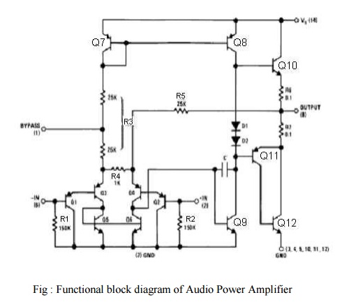
circuit description:
It is
connected of 4 stages,
(i)
PNP emitter follower
(ii)
Different amplifier
(iii) Common
emitter
(iv) Emitter
follower
(i) PNP
Emitter follower:
·
The input stage is emitter follower composed of PNP
transistors Q1 & Q2 which drives the PNP Q3-Q4
differential pair.
·
The choice of PNP input transistors Q1
& Q2 allows the input to be referenced to ground i.e., the input
can be direct coupled to either the inverting & non-inverting terminals of
the amplifier.
(ii) Differential
Amplifier:
·
The current in the PNP differential pair Q3-Q4
is established by Q7, R3 & +V.
·
The current mirror formed by transistor Q7,
Q8 & associated resistors then establishes the collector current
of Q9.
·
Transistor Q5 & Q6 constitute of collector
loads for the PNP differential pair.
·
The output of the differential amplifier is taken
at the junction of Q4 & Q6 transistors & is
applied as an input to the common emitter voltage gain.
(iii) Common
Emitter:
·
Common Emitter amplifier stage is formed by
transistor Q9 with D1, D2 & Q8
as a current source load.
·
The capacitor C between the base & collector of
Q9 provides internal compensation & helps to establish the upper
cutoff frequency of 100 KHz.
·
Since Q7 & Q8 form a
current mirror, the current through D1 & D2 is
approximately the same as the current through R3.
·
D1 & D2 are temperature
compensating diodes for transistors Q10 & Q11 in that
D1 & D2 have the same characteristics as the
base-emitter junctions of Q11. Therefore the current through Q10
& (Q11-Q12) is approximately equal to the current
through diodes D1 & D2.
(iv)(Output
stage) - Emitter follower:
·
Emitter follower formed by NPN transistor Q10
& Q11. The combination of PNP transistor Q11 &
NPN transistor Q12 has the power capability of an NPN transistors
but the characteristics of a PNP transistor.
·
The negative dc feedback applied through R5
balances the differential amplifier so that the dc output voltage is stabilized
at +V/2;
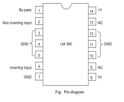
·
To decouple the input stage from the supply voltage
+V, by pass capacitor in order of micro farad should be connected between the
by pass terminal (pin 1) & ground (pin 7).
·
The overall internal gain of the amplifier is fixed
at 50. However gain can be increased by using positive feedback.
Related Topics