Chapter: Linear Integrated Ciruits : Application of ICs
Buck Regulator
Buck Regulator:
The most
commonly used switching converter is the Buck, which is used to down-convert a
DC voltage to a lower DC voltage of the same polarity. This is essential in
systems that use distributed power rails (like 24V to 48V), which must be
locally converted to 15V, 12V or 5V with very little power loss. The Buck
converter uses a transistor as a switch that alternately connects and
disconnects the input voltage to an inductor (see Figure).
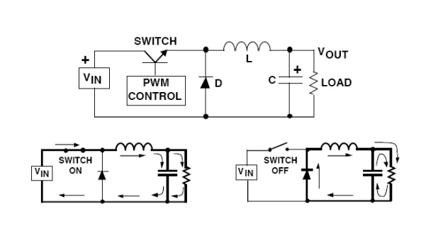
The lower
diagrams show the current flow paths (shown as the heavy lines) when the switch
is on and off. When the switch turns on, the input voltage is connected to the
inductor. The difference between the input and output voltages is then forced
across the inductor, causing current through the inductor to increase. During
the on time, the inductor current flows into both the load and the output
capacitor (the capacitor charges during this time).
When the
switch is turned off, the input voltage applied to the inductor is removed.
However, since the current in an inductor can not change instantly, the voltage
across the inductor will adjust to hold the current constant. The input end of
the inductor is forced negative in voltage by the decreasing current,
eventually reaching the point where the diode is turned on. The inductor
current then flows through the load and back through the diode. The capacitor
discharges into the load during the off time, contributing to the total current
being supplied to the load (the total load current during the switch off time
is the sum of the inductor and capacitor current).
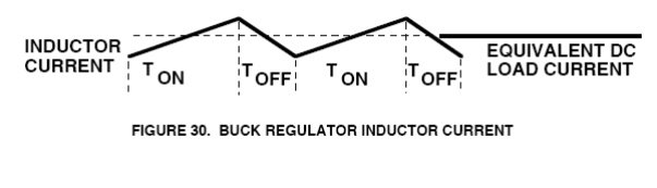
The shape
of the current flowing in the inductor is similar to previous figure. As
explained, the current through the inductor ramps up when the switch is on, and
ramps down when the switch is off. The DC load current from the regulated
output is the average value of the inductor current. The peak-to-peak
difference in the inductor current waveform is referred to as the inductor
ripple current, and the inductor is typically selected large enough to keep
this ripple current less than 20% to 30% of the rated DC current.
Continuous vs. Discontinuous
operation
In most
Buck regulator applications, the inductor current never drops to zero during Full-load
operation (this is defined as continuous mode operation). Overall performance
is usually better using continuous mode, and it allows maximum output power to
be obtained from a given input voltage and switch current rating. In
applications where the maximum load current is fairly low, it can be
advantageous to design for discontinuous mode operation. In these cases,
operating in discontinuous mode can result in a smaller overall converter size
(because a smaller inductor can be used).Discontinuous mode operation at lower
load current values is generally harmless, and even converters designed for
continuous mode operation at full load will become discontinuous as the load
current is decreased (usually causing no problems).
Related Topics