Chapter: Linear Integrated Ciruits : Application of ICs
Generating Multiple Outputs
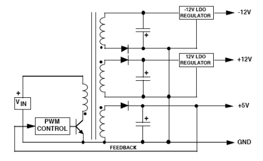
Generating Multiple Outputs:
Another
big advantage of a Flyback is the capability of providing multiple outputs .In
such applications, one of the outputs (usually the highest current) is selected
to provide PWM feedback to the control loop, which means this output is
directly regulated. The other secondary winding(s) are indirectly regulated, as
their pulse widths will follow the regulated winding. The load regulation on
the unregulated secondaries is not great (typically 5 - 10%), but is adequate
for many applications. If tighter regulation is needed on the lower current
secondaries, an LDO post-regulator is an excellent solution. The secondary
voltage is set about 1V above the desired output voltage, and the LDO provides
excellent output regulation with very little loss of efficiency.
The
Push-Pull converter uses two to transistors perform DC-DC conversion. The
converter operates by turning on each transistor on alternate cycles (the two
transistors are never on at the same time). Transformer secondary current flows
at the same time as primary current (when either of the switches is on). For
example, when transistor "A" is turned on, the input voltage is
forced across the upper primary winding with dot-negative polarity. On the
secondary side, a dot-negative voltage will appear across the winding which
turns on the bottom diode. This allows current to flow into the inductor to
supply both the output capacitor and the load. When transistor "B" is
on, the input voltage is forced across the lower primary winding with
dot-positive polarity.
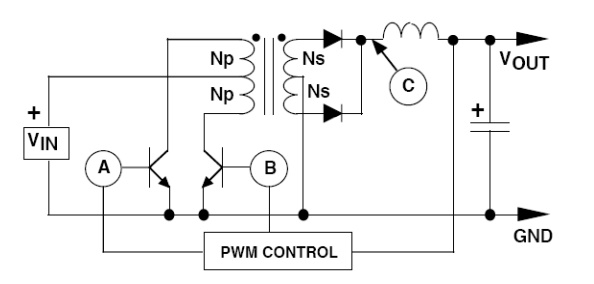
The same
voltage polarity on the secondary turns on the top diode, and current flows
into the output capacitor and the load. An important characteristic of a Push-Pull
converter is that the switch transistors have to be able the stand off more
than twice the input voltage: when one transistor is on (and the input voltage
is forced across one primary winding) the same magnitude voltage is induced
across the other primary winding, but it is "floating" on top of the
input voltage. This puts the collector of the turned-off transistor at twice
the input voltage with respect to ground. The "double input voltage"
rating requirement of the switch transistors means the Push-Pull converter is
best suited for lower input voltage applications. It has been widely used in
converters operating in 12V and 24V battery-powered systems.
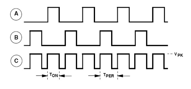
Figure
shows a timing diagram which details the relationship of the input and output
pulses. It is important to note that frequency of the secondary side voltage
pulses is twice the frequency ofoperation of the PWM controller driving the two
transistors. For example, if the PWM control chip was set up to operate at 50
kHz on the primary side, the frequency of the secondary pulses would be 100
kHz. This highlights why the Push-Pull converter is well-suited for low voltage
converters. The voltage forced across each primary winding (which provides the
power for conversion) is the full input voltage minus only the saturation
voltage of the switch. If MOS-FET power switches are used, the voltage drop
across the switches can be made extremely small, resulting in very high
utilization of the available input voltage. Another advantage of the Push-Pull
converter is that it can also generate multiple output voltages (by adding more
secondary windings), some of which may be negative in polarity. This allows a
power supply operated from a single battery to provide all of the voltages
necessary for system operation. A disadvantage of Push-Pull converters is that they require very good matching of the switch transistors to
prevent unequal on times, since this will result in saturation of the
transformer core (and failure of the converter).
Output Capacitor ESR effects:
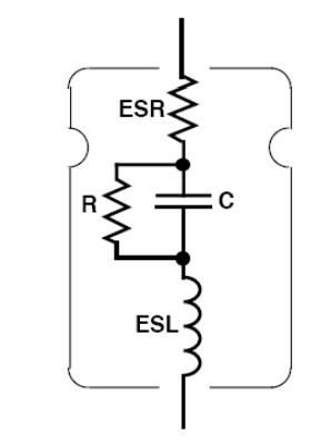
The
primary function of the output capacitor in a switching regulator is filtering.
As the converter operates, current must flow into and out of the output filter
capacitor. The ESR of the output capacitor directly affects the performance of
the switching regulator. ESR is specified by the manufacturer on good quality
capacitors, but be certain that it is specified at the frequency of intended
operation.
General-purpose
electrolytes usually only specify ESR at 120 Hz, but capacitors intended for
high-frequency switching applications will have the ESR guaranteed at high
frequency (like 20 kHz to 100 kHz). Some ESR dependent parameters are: Ripple
Voltage: In most cases, the majority of the output ripples voltage results from
the ESR of the output capacitor. If the ESR increases (as it will at low
operating temperatures) the output ripple voltage will increase accordingly.
Efficiency:
As the switching current flows into and out of the capacitor (through the ESR),
power is dissipated internally. This "wasted" power reduces overall
regulator efficiency, and can also cause the capacitor to fail if the ripple
current exceeds the maximum allowable specification for the capacitor.
Loop
Stability: The ESR of the output capacitor can affect regulator loop stability.
Products such as the LM2575 and LM2577 are compensated for stability
assumingthe ESR of the output capacitor will stay within a specified range.
Keeping the ESR within the "stable" range is not always simple in
designs that must operate over a wide temperature range. The ESR of a typical
aluminum electrolytic may increase by 40X as the temperature drops from 25°C to
-40°C.
In these
cases, an aluminum electrolytic must be paralleled by another type ofcapacitor
with a flatter ESR curve (like Tantalum or Film) so that the effective ESR
(which is the parallel value of the two ESR's) stays within the allowable
range. Note: if operation below -40°C is necessary, aluminum electrolytics are
probably not feasible for use.
Related Topics