Chapter: Linear Integrated Ciruits : Application of ICs
Optocouplers/Optoisolators: Characteristics, Types, Advantages, Disadvantages, Applications
OPTOCOUPLERS/OPTOISOLATORS:
· Optocouplers or Optoisolators is a combination of light source &
light detector in the same package.
·
They are used to couple signal from one point to
other optically, by providing a completer electric isolation between them. This
kind of isolation is provided between a low power control circuit & high
power output circuit, to protect the control circuit.
·
Depending on the type of light source & detector
used we can get a variety of optocouplers.
·
They are
as follows,
(i) LED – LDR
optocoupler
(ii) LED –
Photodiode optocoupler
(iii) LED –
Phototransistor optocoupler
Characteristics
of optocoupler:
(i) Current
Transfer Ratio(CTR)
(ii) Isolation
Voltage
(iii) Response
Time
(iv) Common
Mode Rejection
(i) Current Transfer Ratio:
It is
defined as the ratio of output collector current (Ic) to the input forward
current (If)
CTR = Ic/If
* 100%
Its value
depends on the devices used as source detector. (ii) Isolation voltage between
input&
output:
It is the
maximum voltage which can exist differentially between the input & output
without affecting the electrical isolation voltage is specified in K Vrms with
a relative humidity of 40 to 60%.
(iii)Response
Time:
Response
time indicates how fast an optocoupler can change its output state. Response
time largely depends on the detector transistor, input current & load
resistance.
(iv)Common
mode Rejection:
Eventhough
the optocouplers are electrically isolated for dc & low frequency signals,
an impulsive input signal (the signal which changes suddenly) can give rise to
a displacement currentIc= Cf*dv/dt. This current can flow between input &
output due to the capacitance Cf existing between input & output. This
allow the noise to appear in the output.
Types of
optocoupler:
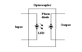
(i) LED –
Photodiode optocoupler:


·
LED photodiode shown in figure, here the infrared
LED acts as a light source & photodiode is used as a detector.
·
The advantage of using the photodiode is its high
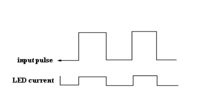
linearity. When the pulse at the input goes high, the LED turns ON. It emits
light. This light is focused on the photodiode.
·
In response to this light the photocurrent will
start flowing though the photodiode. As soon as the input pulse reduces to
zero, the LED turns OFF & the photocurrent through the photodiode reduces
to zero. Thus the pulse at the input is coupled to the output side.
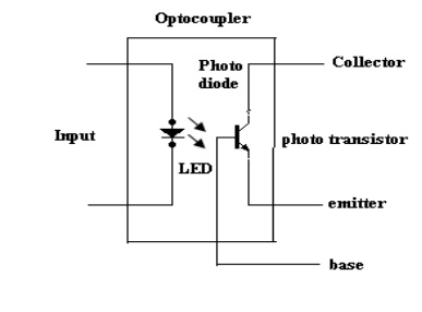
(ii) LED
– Phototransistor Optocoupler:


·
The LED phototransistor optocoupler shown in
figure. An infrared LED acts as a light source and the phototransistor acts as
a photo detector.
·
This is the most popularly used optocoupler,
because it does not need any additional amplification.
·
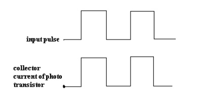
When the pulse at the input goes high, the LED
turns ON. The light emitted by the LED is focused on the CB junction of the
phototransistor.
·
In response to this light photocurrent starts
flowing which acts as a base current for the phototransistor.
·
The collector current of phototransistor starts
flowing. As soon as the input pulse reduces to zero, the LED turns OFF &
the collector current of phototransistor reduces to zero. Thus the pulse at the
input is optically coupled to the output side.
Advantages of Optocoupler:
·
Control circuits are well protected due to
electrical isolation.
·
Wideband signal transmission is possible.
·
Due to unidirectional signal transfer, noise from
the output side does not get coupled to the input side.
·
Interfacing with logic circuits is easily possible.
·
It is small size & light weight device.
Disadvantages:
·
Slow speed.
·
Possibility of signal coupling for high power
signals.
Applications:
Optocouplers
are used basically to isolate low power circuits from high power circuits.
·
At the same time the control signals are coupled
from the control circuits to the high power circuits.
·
Some of such applications are,
(i) AC to DC
converters used for DC motor speed control
(ii) High
power choppers
(iii) High
power inverters
·
One of the most important applications of an
optocoupler is to couple the base driving signals to a power transistor
connected in a DC-DC chopper.
·
Note that the input & output waveforms are 180º
out of phase as the output is taken at the collector of the phototransistor.
Related Topics