Chapter: Civil : Principles of Solid Mechanics : Rings, Holes, and Inverse Problems
Solution Tactics for Neutral Holes- Examples
Solution Tactics
for Neutral Holes- Examples
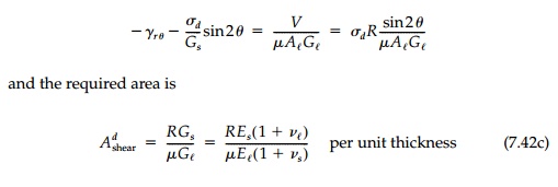
For the inverse
problem, a solution matching displacements at the interface using the integral
equations, will necessarily be one of trial and error even for an assumed shape
since the unknown geometric properties of the cross-section will, in general,
be functions of position and must remain inside the integral. A better tactic
is to enforce compatibility on a differential scale by
using Equations (7.34)
with Equations (7.31) and (7.32). The displacements will then necessarily
conform aside from initial conditions u0, v0,
and _0.
These along with any unknown integration constants in the equilibrium equations
can then be found in the standard way once the geometry of the hole and liner
is known.
The theory as presented
essentially reduces to a ŌĆ£strength-of-materialsŌĆØ solution for a ring where the
geometry of its deformation must match that of the sheet at the interface. It
is, of course, approximate to the extent that all strength-of-material
solutions are approximate. Thick-ring effects could eas-ily be incorporated if
necessary by including the eccentricity of the neutral axis and adding the
bending contribution at the interface.
However, as is usually
done, the equations will be simplified further by neglecting the curvature
contribution and reducing the liner to the ŌĆ£elasticaŌĆØ at the neutral axis. The
significance of this ŌĆ£thin ringŌĆØ assumption can be esti-mated by considering a
circular liner of radius R in an isotropic field.
For this situation the
ring simply expands uniformly and, since there is no 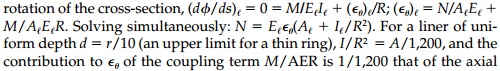 force
force
N/AE.
Thus, the final term in the first two equations of Bresse will be negligible
and will not be included hereafter.
Two special cases of
obvious importance will be considered in the examples that follow. First,
membrane reinforcement may be possible in certain fields by adjusting the hole
shape to ŌĆ£eliminateŌĆØ bending. This is the Mansfield solu-tion and, as shown
previously, can occur only for that shape which is a level line of U
given by Equation (7.32). This ŌĆ£short-circuitsŌĆØ the equations of Bresse in that
if V =0, both ╬╝ and I are
indeterminate. The area required can be found directly from Equations (7.34a)
with (7.35a). However, an actual liner will have some bending stiffness
inducing secondary moments (i.e., a gradient of normal stress through the
thickness) violating the original membrane assumption. This dilemma, not
considered by Mansfield, is a direct result of the strength-of-materials
approach. Such secondary effects will be shown to be very small for thin
liners.
Circular liners are a second important class of potential solutions. In this case the shape is prescribed and I l, A l, and ╬╝ are to be determined to satisfy the neutral condition. The strains in the sheet in polar coordinates r, and ╬Ė become:
Similarly, since the
radius is a constant, the differential equations of Bresse are easily solved
for the required liner properties.
Isotropic Field
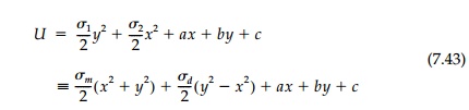
With equal normal stress in orthogonal directions, Žām,
the stress function is:
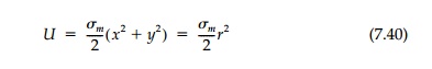
and the obvious shape is circular. Thus, by the
equilibrium equations
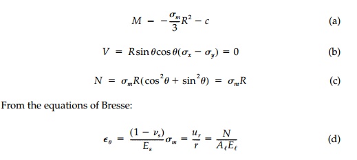
which is not possible if M = 0. However, we know from Lam├®ŌĆÖs exact solu-tion that there is, in fact, a
constant moment in the ring since the hoop stress is not uniform through the
thickness. Combining (c) and (d):
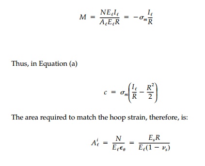
per unit thickness which we derived earlier.
There will be no requirement on the moment of
inertia. Thus, a ŌĆ£neutralŌĆØ liner will have a uniform cross-section and be
ŌĆ£thinŌĆØ as defined by d/r " 10 if Es/El(1-vs) < 10.
This is nearly true for a steel liner in concrete or rock and true for a
concrete or steel liner in soil.
Deviatoric Field
For the pure shear or deviatoric field with equal
but opposite principal stresses, +-
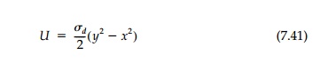
Therefore, the membrane
shape is a self-equilibriating system of parabolic ŌĆ£archŌĆØ and ŌĆ£suspensionŌĆØ
segments which, while conceivable, is not likely in practice.
On the other hand, a circular, neutral liner may be
feasible. Using cylindri-cal coordinates where
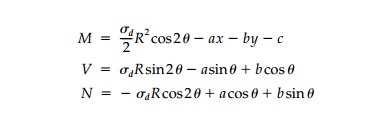
Through symmetry the
moment at the springing line must be equal and opposite that at the
crown. Thus, c must be zero. Therefore, the stress resultants in the
liner are
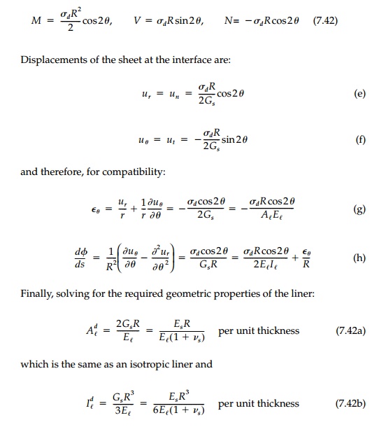
These results are startling. It is possible to
design a neutral circular liner com-pletely restoring the original field, which
has constant A and I, and therefore, is easy to build. Checking
shear compatibility from Equation (7.34c)
This is close to that required by Equation (7.42a)
in order to match the hoop strain since
A 10 WF 17 would give
the required moment of inertia, but over 100 times too much area, and slip
joints to reduce the effective A would be necessary. Clearly, as one
might expect for a circular shape in pure shear, bending dominates entirely and
we might term this remarkable neutral liner with constant cross-section the
flexural counterpart to the circular, axial-force liner for the isotro-pic
field.
General Biaxial Field
A general biaxial field will be a combination of
isotropic and deviatoric com-ponents. Assuming that the x axis is in the
direction of the maximum princi-pal stress:
Thus, the membrane shape will be a combination of a circle and parabola. The hole boundary can only be closed if Žām > Žād, in which case an ellipse results with the principal axes in the ratio a/b = Rt(Žā1 / Žā2) . This important and practical case is given by Mansfield, but was actually found nearly a century before by Rankine using parallel projection.
![]()
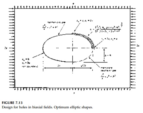
The neutral shape and
liner for no stress concentration is compared to the unlined harmonic shape
(stress concentration of 1.5) in Figure 7.13a for a 2 to 1 biaxial field. If vs
is 1/4, then the area of the membrane liner at the ŌĆ£spring-ing lineŌĆØ (i.e., y = 0) would be about 2.5 times that required at the ŌĆ£crownŌĆØ (i.e., x = 0). If E_/Es=1,000 and R is 10 ft, then the A_,
at the springing line, should be 0.34 in.2/in. (219 mm2/mm).
This is roughly that of the average corrugated plate section now used in
practice for large-span elliptic culverts and arches in soil (Figure 7.13b).
Therefore, if the axial stiffness were gradu-ally reduced by a factor of 2.5
from the springing line to the crown in such structures by slip joints or by
using lighter plates, the moments could be ŌĆ£eliminatedŌĆØ and the design improved
to the neutral case.*
For a shape other than
the membrane ellipse, moments will be introduced and the liner must also have
the correct flexural stiffness to achieve neutrality. Equations based on the
general theory and conditions for their existence can be derived and studied.
However, from a practical design standpoint, it is doubtful if such
intermediate cases are as useful as the four special cases:
1. Harmonic
hole ellipse (7.25)
2. Rigid
harmonic inclusion ellipse (7.26)
3. Membrane neutral ellipse (a/b Rt(Žā1/ Žā2)
)
4. Flexurally neutral circle (7.42)
If a hole is to be
placed in a loaded body (e.g., a tunnel), the harmonic shape may be preferable
to minimize stress concentration in the sheet and then rein-forcement provided
to take active loads. For a sheet with a reinforced hole that is then loaded
(e.g., buried pipe or most structural applications in plates and shells), the
designer would normally choose the membrane configuration or, for ease in
construction, a circle. Only if forced to use a rigid liner, would the designer
choose the harmonic inclusion shape.
Gradient Fields with
an Isotropic Component
In many engineering
applications, there is an isotropic component in the stress field in addition
to the gradient induced by bending or geostatic conditions. This is the general
case in pressure vessels, shell structures or masonry walls, tunnels, pipe, or
in other buried structures. For this case the stress function becomes
Although Mansfield does
not consider this case, a simple closed membrane shape is possible if the
stress function can be put in the form:
which, when equal to
zero, gives the neutral hole shape. To do this let: x = fxo and y = yo,
where xo, and yo refer to points on the
circle of radius R and f is the ŌĆ£mapping functionŌĆØ which
transforms this circle to the membrane shape. The stress function [Equation
(7.44)] can then be rewritten:
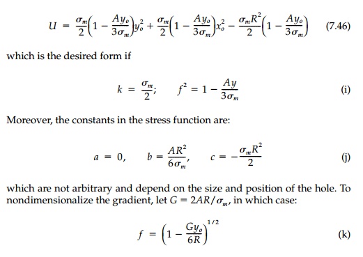
limiting the possible gradient field for a membrane
shape to G " 6.
A more stringent
limitation is imposed by the area required of the liner for compatibility. The
normal force in the liner is by Equation (7.31a)
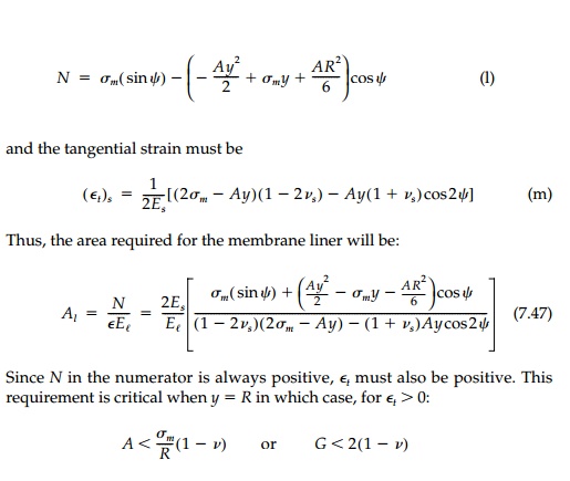
giving a much more
severe restriction on the size of a neutral membrane hole that can be put in
any given gradient field.
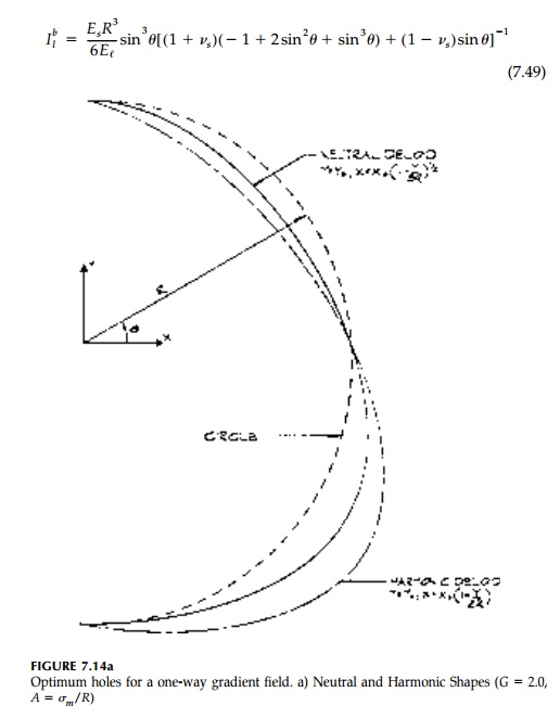
The neutral ŌĆ£deloidŌĆØ
shape giving no stress concentration with a mem-brane liner, is compared in
Figure 7.14a to the harmonic deloid for an unlined hole for the extreme case, G = 2. They are both of the same generic type, but the neutral shape is much closer
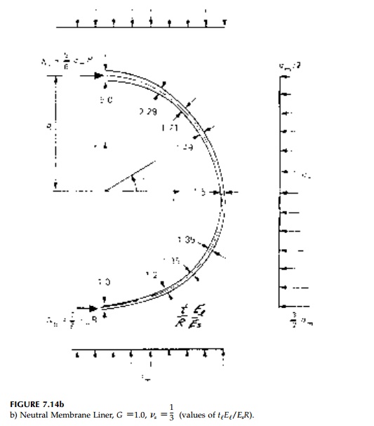
to a circle. The non dimensionalized area required of the membrane liner for G=1.0, v=1/3 is shown in Figure 7.14b. Comparing the result to the membrane liner for a
circular hole in an isotropic field where ElA/EsR = 1.5, this neutral deloid design is, for a gradient field, just as feasible.
Even for a concrete liner in stiff soil where El/Es
might be 100, the depth of a prismatic liner for a 20 ft diameter opening would
be only 1.2 in. at the bottom, 1.8 in. at mid-height, and 6 in. at the top.
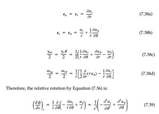
To achieve a circular
neutral liner, rotation compatibility is critical in that
with a, b,
and c all zero by symmetry arguments. The rotation of the sheet at the
interface by Equation (7.36) is
Therefore, designing a
liner for a circular neutral hole in a gradient field is not practical since
the moment of inertia required is slightly negative near the neutral axis
(unless vs = 0). However, this might be feasible in concrete or steel where the sheet near
the neutral axis could be made thinner.
Summary
It has been possible to
extend the Mansfield theory for membrane neutral lin-ers to the general case of
flexural reinforcement. The resulting expressions for equilibrium and
compatibility in terms of the stress function U for the sheet are, in
fact, not limited to the neutral condition, but are valid for any thin
rein-forcement and thus, are fundamental to the general interaction problem.
In the classical
interaction problem, the total, U = Uo + U*, is unknown
since the perturbation in the field U* due to the hole in unspecified.
By inverting
the problem to a design
mode where U* is specified (to be zero for the neutral condition), the
stresses, strains, and displacements in the field are entirely known, as are
the stress resultants in the liner. Thus, the tangential strain and the
rotation of the liner can be found from the equations of Bresse and matched at
the interface to the same known quantities in the field to give expressions for
the required liner area and bending stiffness.
Closed-form solutions
are given here for both the circular and the mem-brane shape for a variety of
free fields. A review of these results reveals two interesting limitations to
achieving, at least in a simple way, the neutral con-ditions with a thin
continuous liner: Most important is the ŌĆ£Poisson ratio effect.ŌĆØ For a positive
area of the liner: ( t)s must be exactly in
phase with N, i.e., have the same sign at every point on the interface.
This might seem obvi-ous, but apparently was not recognized by Mansfield in his
work on mem-brane reinforcement. Similarly, if there is bending, the rotation
change (dŽĢ/ds)s
must be exactly in phase with M to have a positive moment of inertia.
Thus, only in special cases such as the purely deviatoric field or biaxial
bending can a neutral liner be found for a ŌĆ£simpleŌĆØ closed hole in a region of
a field where either U or its gradient change sign or even approach
zero.
Within this constraint,
neutral liner designs are found for two basic situa-tions important in
practice: (1) Circular holes in deviatoric and biaxial fields (flexural liner);
and (2) membrane ŌĆ£deloid shapeŌĆØ and liner for the gradient field with an
isotropic component. The second case is particularly useful in that it allows a
design within a bending field and closely resembles the geo-static field
condition for shallow pipes and tunnels. Moreover, since the ŌĆ£deloidŌĆØ neutral
shape is of the same generic type as the harmonic hole for minimum stress
concentration with no liner, its use may serve a double pur-pose both in
construction to reduce stresses around the hole and then with reinforcement to
best withstand gradient service loads.
Related Topics