Chapter: Civil : Principles of Solid Mechanics : Wedges and the Half-Space
Concentrated Loadings at the Apex
Wedges and the Half-Space
Structures that can be idealized to wedges are found at every scale from mas-sive gravity dams to gear teeth. Moreover, for wedge angles greater than 90_, no strength-of-materials type analysis is possible and only for very small angles should we expect such simplified analysis to give even a decent approximation. Therefore, as for thick rings and plates with small holes, two-dimensional solutions from elastic field theory are mandatory for the design of such structures.
Concentrated Loadings at the Apex
Consider first a wedge of angle 2_ in plane stress such as shown in Figure 8.1 with an axial load, P, at the apex. If the wedge angle were very small, then we might expect 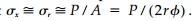 . Let us assume, then, a stress func-tion of type III:
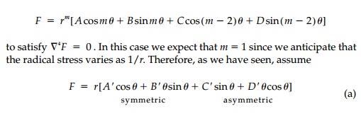
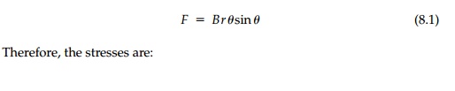
But we know the stresses must be symmetric with θ and the first term gives nothing so, through this physical reasoning process, we can deduce that:
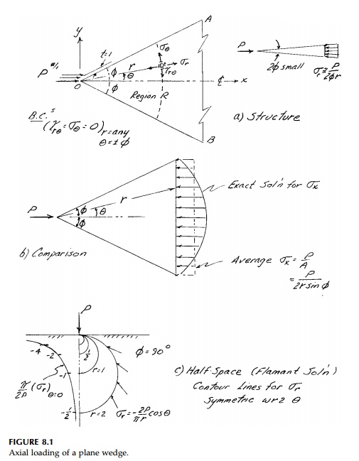
A comparison of σx from the elasticity solution to the average value σx = P/A is shown in Figure 8.1b. We see that only for small wedge angles is the strength-of-materials approximation adequate.
This solution when applied to the half-space is particularly important as it corresponds to the punch or bearing capacity situation. It also serves as one of the fundamental building blocks for 2D boundary-element modeling. The result for ϕ2 = π, often called the Flamant Solution,
is shown in Figure 8.1c. The stresses die off as 1/r and the isopachics and iso-chroniatics (contour lines of equal σ1 + σ2 and σ1 - σ2) are identical circles:
The load, P, must actually be distributed over a small “circular” area near the apex in which plastic flow takes place redistributing the stress to its yield
value at r=ryield. Outside this plasticized zone the strains can be computed from the stresses using the elastic relationships and integrated to determine displacements.*
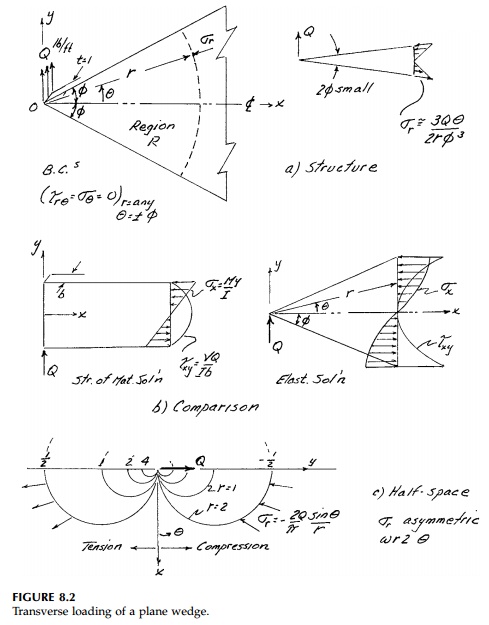
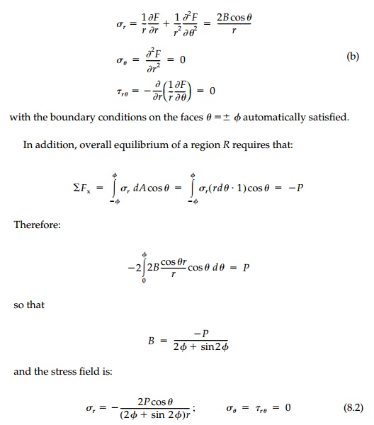
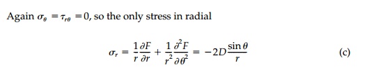
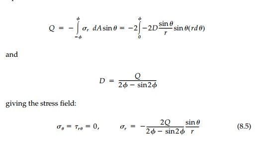
For a vertical transverse load Q at the apex, the reasoning is similar. For a very small wedge angle, we would expect that σr == σx == My/I where, as shown in Figure 8.2, M = Qr, y = rθ, and I = (2rφ)3/12. Therefore σ r =3Qθ/2rφ3 , so again the radial stress dies off as 1/r and we should assume m = 1 in the stress function (a). In this case, however, since there is bending and no axial force, only the asymmetric terms apply. The term Crsinθ gives no stress and therefore:
The boundary conditions like the overall moment and axial-force equi-librium requirements are already satisfied in Region R but to satisfy vertical equilibrium:
For any significant wedge angle, a strength-of-material approximation is unsatisfactory. For the half-space, Q becomes a concentrated shear producing radial stress bulbs,
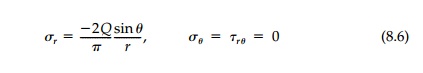
as shown in Figure 8.2c. They are identical to those for P but 90o out of phase.
Clearly the solutions for concentrated line loads P and Q at the apex of a wedge can be superimposed to give the field for a line load at any inclination. Moreover, a line load within an “infinite” elastic body (ϕ=π), sometimes called the Kelvin Problem, can also be solved.*
Finally let us solve for the stresses in a wedge with a concentrated line moment at the apex (Figure 8.3). Again, considering a narrow wedge with ϕ
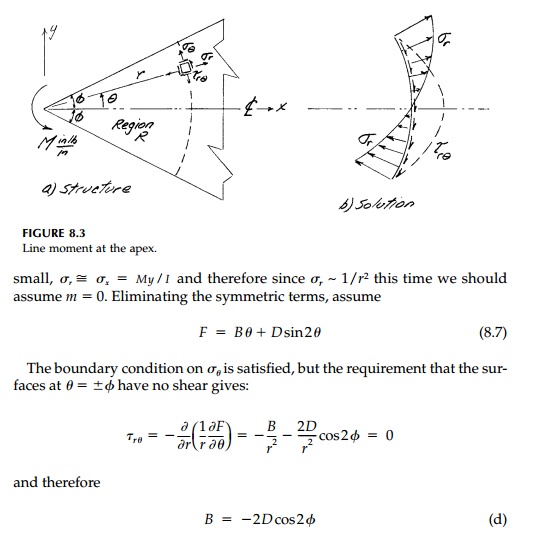
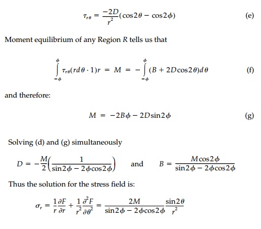
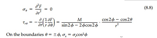
so that the strength-of-materials approximation breaks down quickly for significant wedge angles. The compar-ison of normal stress is similar to that for a transverse load in Figure 8.2b, but the shears are very different. More significant, perhaps, is that the field is highly localized near the point of application since the stresses induced by the moment die off as 1/r2 compared to 1/r for a concentrated load.
For larger wedge angles the solution is suspect. At 2ϕ=257.4o the denominator sin2ϕ = 2ϕcos2ϕ goes to zero and the solution blows up. Sternberg and Koiter term this ambiguity in the two-dimensional solution for a line moment on a wedge for 2ϕ>πa paradox, which they do not entirely resolve. We shall see that such ambiguity is present in a number of wedge solutions and that all questions in “simple” two-dimensional elasticity theory are not yet answered.
Example 8.1
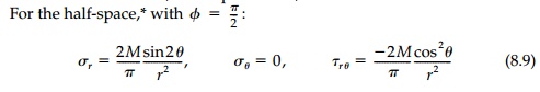
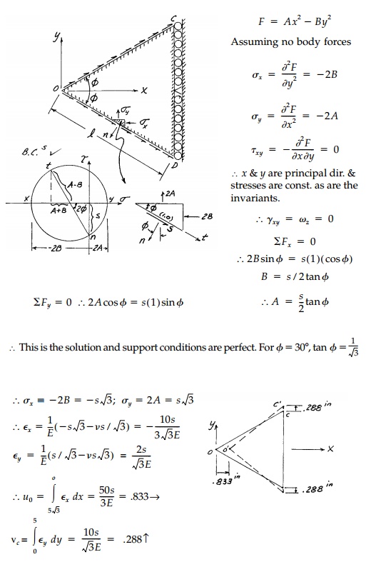
A tapered Epoxy beam (wedge) in plane stress is loaded by shear trac-tions of s on the upper face and -s on the lower face as shown. The stress function F = Ax2 - By 2 is proposed. Evaluate A and B and show that this is the solution. Are the support conditions appropriate? For v = 1/3, E = 200,000 psi determine the deformed shape of a 60o wedge (2ϕ=60o) if l=10 ft. for s=10,000 lb/ft per inch thickness. Sketch the deformed shape.
Related Topics