Chapter: Civil : Principles of Solid Mechanics : Wedges and the Half-Space
Wedges with Constant Body Forces
Wedges with
Constant Body Forces
Gravity loading of
massive concrete, stone, and soil structures often produce the largest components
of stress for which the designer must provide. For slopes, retaining walls, and
geologic formations, body force may, in fact, be the only load. Seismic loading
is often approximated by the assumption of a constant acceleration applied to
the structure and even when the acceleration is not constant, the assumption of
a constant peak value gives the engineer a worst-case estimate.
A solution can be obtained in polar coordinates, but is more clearly pre-sented in the Cartesian reference frame shown in Figure 8.10. Letting γx and γy be the body-force components due to gravity in the subscripted directions and K = tanβ, the stress function:
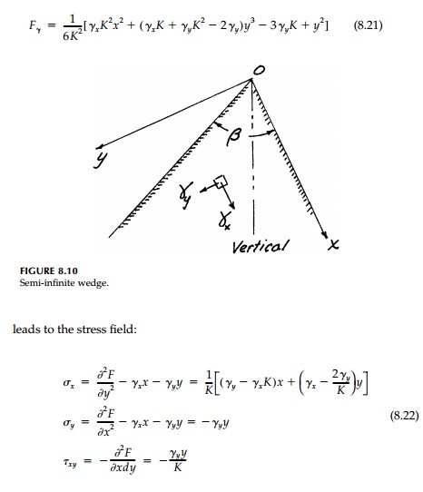
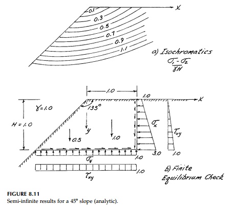
This is a wonderfully simple solution since it predicts a linear stress field. Therefore Ɐ2(σx + σy ) = 0 in a “trivial” fashion. We see, however, that the so-called “paradox of elasticity” we discovered in Section 8.2 again appears since for the half-space β = 180o, K = 0, and the solution blows up. In fact, for wedges where β>90o, this solution probably does not exist. Shown in Figure 8.11 are the analytic results for a 45o slope, which are certainly peculiar. The normal stress becomes larger and larger along the upper horizontal face as the distance from the crest, x, increases. This is nonsense. Yet as shown in Figure 8.11b, the seemingly unrealistic result certainly does give equilibrium and satisfy the boundary conditions on the exposed faces of the wedge.*
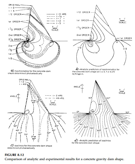
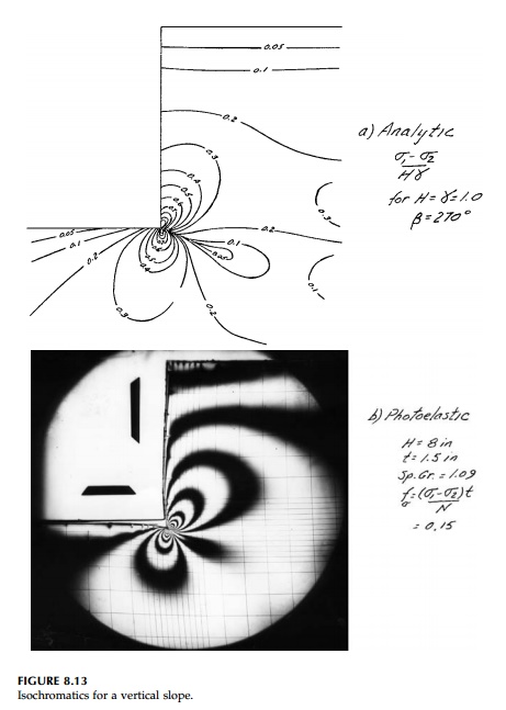
On the other hand, at β>= 90o the analytic solution is perfectly reasonable and is used in the design of concrete gravity dams. Figure 8.12 shows a comparison of the analytic solution and experimental results for a gelatin model for a concrete dam shape in terms of isochromatics and isoclinics. The agreement is excellent. The same is true for a vertical cut (β= 90o) shown in Figure 8.13.
It would appear then that this “paradox” is a problem with uniqueness, which, in retrospect, is not surprising. From our discussion in Chapter 4 of the Laplace equation Ɐ2(σx+ σy) = 0, we know that we can only guarantee a unique solution if we specify proper conditions over a closed boundary. Since no con-ditions are specified at r= l arge in any of these wedge solutions, we must be
skeptical of results where the stress
field does not either damp out as r �' or approaches the free
field.
Example 8.3
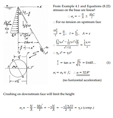
A concrete gravity dam with a vertical
upstream face is to be built so that, with a full reservoir, there will be no
tension and an adequate factor of safety against crushing ( f'C=1125
psi = allowable compressive stress).
Knowing from our
elasticity wedge solutions that the stresses will be distributed linearly over
every horizontal cross-section, and assuming γw
(water) = 62.4 lb/ft3, γc(concrete) = 150 lb/ft3, design the dam; i.e., determine:
i. the optimum angle
ii. the maximum permissible height zmax = H
Solve for the case of
no horizontal acceleration and also for the case of a hor-izontal acceleration ax = p kh g with kh = 0.3.
Comment on your results knowing that
Shasta Dam in Northern California, (the highest gravity dam in the U.S.) is 580
feet high at an angle α = 36o and was supposedly designed “at the limit” for such a concrete.
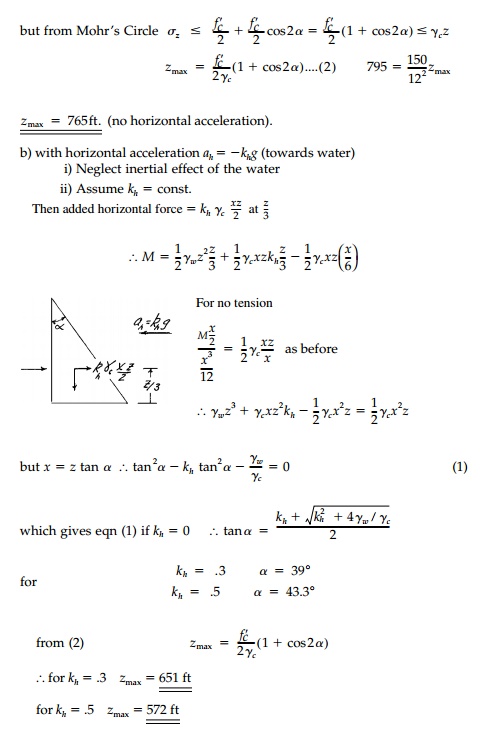
Shasta Dam is a good design. Actu-ally Shasta Dam looks more like the illustration at right. Concrete will take some tension and downward water force, Fw , will reduce or eliminate seis-mic tension at the heel. By bringing the downstream slope toward the vertical σt �' σz reducing crushing. Highest gravity dam is in Switzerland (no earthquakes) at z max > 900 ft. Reason- able since if σz = σy t, z max = fc′ /γc = 1080 ft with stronger concrete even greater heights are possible in non seismic zones.
Related Topics