Chapter: Civil : Principles of Solid Mechanics : Rings, Holes, and Inverse Problems
Neutral Holes
Neutral Holes
For both unlined holes
and rigid inclusions, it is possible to leave the geom-etry of an opening
unspecified thus inverting the standard problem in elas-ticity to solve for
shapes to achieve an optimum design specification on the final stress state.
The design criterion that has been used so far, the har-monic field condition,
specifies that the first invariant of the stress tensor, satisfying Laplace’s
equation, remain everywhere unperturbed when the shape with unknown boundary
loading or displacements is introduced. Such shapes for holes or inclusions,
termed “harmonic shapes,” apparently produce the minimum stress concentration
possible in any given free field. These are, therefore, optimum for the cases
where there is either no liner or the liner is rigid.
Between the two
extremes of no liner or a rigid hole interface, it may be possible to find a
flexible liner designed such that all perturbation of the field is eliminated.
In this case using the same inverse strategy, not only is the shape unknown,
but so are the stiffness properties of the liner. However, in this case as
recompense for the added unknowns, both the deviatoric and iso-tropic
components of the stress and strain and all displacements are known everywhere
since they are the same as the uncut sheet.
The combination of hole
shape and liner stiffness to give complete field restoration through structural
equivalency is a special subset of harmonic shape called a “neutral hole” by
Mansfield. He was the first to clearly define
this inverse problem
and develop a theory for the special case of membrane reinforcement. A more
general theory, with examples where flexural as well as axial stiffness of the
liner is included, should be of immediate practical consideration for new
design in almost every area of structural mechanics where eliminating all
stress concentration will lead to less material.*
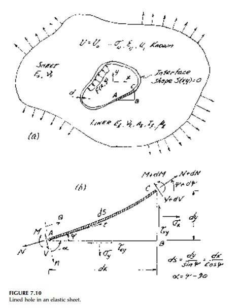
The parameters of the
problem are shown in Figure 7.10. Making the “sim-plest” assumptions of
two-dimensional elasticity theory without body forces, the inverted problem for
the neutral hole can be stated as shown in Table 7.1
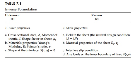
where the symbol U
is used for the stress function rather than F so as not to confuse it
with the boundary loading.
The properties of the
liner required to achieve the neutral condition will of course depend on all
the “known” variables. Let us confine ourselves here to a straightforward but
realistic and powerful specification of these variables.
1. Field
stresses (and, therefore, strains and displacements) will remain unperturbed in
every respect (i.e., the liner will behave exactly as the material did in the
cavity into which the liner is placed).
2. Only
the general biaxial and linear gradient free fields will be considered.
3. Material
properties are constant and the modulus ratio, El/Es,
is such that the liner can be considered a “thin” ring (i.e., radius to
thickness ratio R/d > 10).
4. A
no slip condition exists at the interface.
5. The
inner surface of the liner is not loaded [i.e., F(x,y) = 0].
Within this framework,
the problem may be “underspecified” for a unique solution emphasizing the
“design” nature of this approach.
Generalizing
Mansfield’s derivation to include flexural stiffness, consider first the
equilibrium of the diferential element of the liner shown in Figure 7.10b:
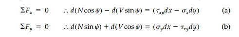
However, since the
right hand side of Equations (a) and (b) are total differen-tials in terms of
the stress function, U, they can be integrated to give:
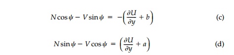
in which (a) and (b)
are arbitrary constants. Solving for the normal and shear force resultants
separately:
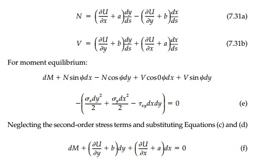
Thus, with Equations
(7.31), the internal force resultants and moment can be determined for the
liner for a prescribed shape in any given field, U, inde-pendent of
material properties. Since terms such as ax, by, and c can
be added to U without affecting stresses in the sheet, they can be used
to adjust the V, N, and M diagrams or the position and
size of the hole. For the case of a neu-tral membrane liner without flexural
stiffness, Mansfield’s equation for the neutral shape is obtained directly from
Equation (7.31c) as
if the arbitrary constants are neglected.
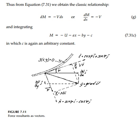
These basic equilibrium
equations can also be considered in terms of vector components as shown in
Figure 7.11 where t and n are unit tangent and nor-mal vectors.
If we neglect the arbitrary constants a, b, and c, and
define the vector g = Pi + Qj = grad U, the internal force equilibrium
conditions are simply that N and V are the magnitudes of the
normal and tangential compo-nents of the directional derivative of U.
That is
If for membrane
reinforcement the moment is zero, then the shear must be zero and the neutral
shape is a level line of U.
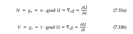
It should be emphasized
that equilibrium Equations (7.31) apply in gen-eral to any liner or, for that
matter, all problems involving a flexible member interacting with an elastic
medium. As such they are quite remarkable in that they give a physical
interpretation of the stress function and its gradient at the interface.
However, only for the inverse problem where U is known
(or perhaps for the
standard problem if the moment and force resultants were measured
experimentally) is it possible to use them directly.*
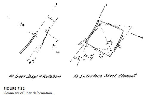
Displacements of the
liner and strains at its neutral axis due to the internal moment and force
resultants can now be found by the so-called “generalized equations of
Bresse.”** The cross-section will be displaced and will rotate as shown
positively in Figure 7.12a. Considering a differential length, assuming plane
sections, and neglecting any contribution from the normal expansion or
contraction of the liner, then in curvalinear coordinates:
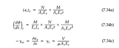
in which the final
equation includes only the contribution to un due to shear
“warping.” To obtain the displacements of the liner, these equations must be
integrated along its length in the usual fashion.
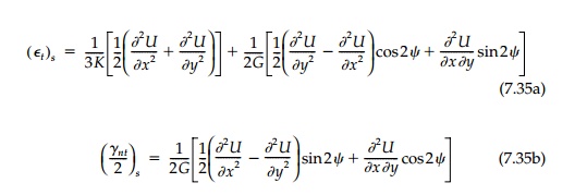
Finally for the sheet,
the strain components, (E ij)s, can be
obtained directly from the stresses which, in turn, can be converted to
stress-function relationships by the standard definition and transformation.
Doing this for only those compo-nents necessary for the compatibility match:
The rotation of the
sheet at the interface, as shown in Figure 7.12b, is given directly by
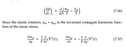
the relative rotation
of the interface [by Equation (7.19)] can also be expressed in terms of the
stress function. Displacements of the sheet, (ui)s,
can be found by integrating the strains directly.
Related Topics