Chapter: Civil : Railway Airport Harbour Engineering : Railway Engineering : Modern Methods of Railway Track Maintenance
Principles of Working of Railway On track Tampers

On-track Tampers
On-track tampers are
self-propelled vehicles which facilitate automatic tamping of sleepers through
the controls provided in the operator's cabin. Heavy on-track tampers weigh 20
to 30 t and cannot be easily removed from the track. It is therefore vital that
the work be done after putting up the necessary traffic blocks. However, the
tamper can be put off the track using special equipment, provided that there
are adequate bank extensions available. These tampers can automatically and
simultaneously perform the tasks of lifting, aligning, levelling, and tamping.
On American railroads, a sleeper is referred to as a tie. Therefore, since
on-track tampers are used for tamping sleepers (or ties), they are also called tie
tamping machines.
Principles of Working of On-track
Tampers
The principles of the working of
an on-track tamper (tie tamping machine) are described below.
Tamping
Tamping is the most important
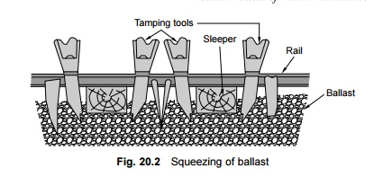
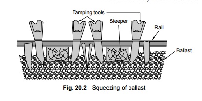
application of tie tamping (TT) machines. Tamping consists of packing the
ballast under the sleeper. This is achieved by vibrating the ballast, thereby
making it fluid, and then compressing it by squeezing as shown in Fig. 20.2.
Tamping is done with the help of either 16 or 32 tamping tools, depending upon
whether single or double sleepers are to be packed at a time. Tamping is done
by either the synchronous or the non-synchronous system of vibration. In the
synchronous system, the movements of the two tamping tools on either side of a
sleeper are similar and simultaneous, synchronizing with each other. In the
case of non-synchronous systems, the two tools work independently.

Aligning the track
The alignment of the track is
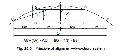
corrected by the two-chord system in the case of machines manufactured by
Messrs Plasser and Theurer. In this method, two chords of lengths 24 m and 12 m
are taken and placed in the area between two rails, where they are stretched
parallel to the track and kept a certain distance apart from each other.

It can be geometrically proved
that the versine BQ of the short chord AC measured at a quarter point B' is
one-third of the ordinate BB ' measured for a long chord at the same
quarter point (Fig. 20.3). The ordinate at the quarter point of the 24-m chord H
and the versine at the centre of the 12-m chord h are measured using a
measuring bogie. In a circular curve, the ratio of H:h is equal
to 3:1 as indicated above. The two dimensions are measured at the same point by
means of the measuring bogie and if the ratio is found to be equal to 3:1, it
indicates that the curve is in order and that the alignment is correct. In the
case of any defects, special rollers attached to the rail are used to slew the
track at the location of the centre bogie till this ratio is achieved.
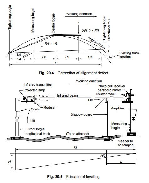
This procedure is used for
correcting alignment defects to a value that is one-sixth the value of the
original fault because of the relative positions of the measuring bogie and the
central bogie as shown in Fig. 20.4. The latest TT machines can be used to
correct alignment defects using the three-chord and four-chord methods.
Levelling
Longitudinal levels are corrected
on the basis of the principle of proportional levelling with the help of
tampers along with an infrared transmitter, a shadow board, and photocells. The
distance between these three units is fixed and is so arranged that any error
in the longitudinal level is reduced to one-fifth of its value, as is clear
from Fig. 20.5.

Related Topics